Chuck D. Bones
Circuit Wizard
I've been meaning to breadboard the Phase 90 for a long time. Anyone who has played thru one of these knows about the ethereal, liquid, tone.
I recall tracing one of these when I was an engineering student back in 1976. I had read about using JFETs as variable resistors, but this was the first time I had seen someone actually do it.
I built the breadboard in accordance with the PPCB XC Phase schematic with the following exceptions:
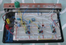
All four blue rails are ground. The bottom two and top red rails are Vcc. The 3rd red rail is Vref. SCRIPT switch is on the right. Center is Script Logo, down is Block Logo and up is high Q (stronger feedback than Block Logo). I rearranged the opamps a bit. The chip on the far right is the input buffer and the 1st phase-shift stage. Middle chip is the 2nd & 3rd phase-shift stages. Chip on the far left is the 4th phase-shift stage and LFO.

There is a good analysis of the Phase 90 over at ElectroSmash and also a cool interview with Don Morris, one of MXR's engineers.
I recall tracing one of these when I was an engineering student back in 1976. I had read about using JFETs as variable resistors, but this was the first time I had seen someone actually do it.
I built the breadboard in accordance with the PPCB XC Phase schematic with the following exceptions:
- I connected a Throb LED to IC3-7.
- Q5 is a 2N5087, just like in the Phase 90 I traced.
- C8 is 10uF tantalum. I was out of 15uF caps. MXR uses a tantalum cap and for good reason. A leaky LFO cap could cause the LFO stall.
- C10 is 22uF aluminum. This cap filters Vref and it's value and material are not critical.
- The bias trim is a 100K trimpot with a 100K resistor at each end. It is much less touchy this way.
- I omitted the STAGES switch.
- I used an ON/OFF/ON switch for the SCRIPT switch to get two levels of feedback (or no feedback).
- I omitted D1 because it doesn't do anything.
All four blue rails are ground. The bottom two and top red rails are Vcc. The 3rd red rail is Vref. SCRIPT switch is on the right. Center is Script Logo, down is Block Logo and up is high Q (stronger feedback than Block Logo). I rearranged the opamps a bit. The chip on the far right is the input buffer and the 1st phase-shift stage. Middle chip is the 2nd & 3rd phase-shift stages. Chip on the far left is the 4th phase-shift stage and LFO.

There is a good analysis of the Phase 90 over at ElectroSmash and also a cool interview with Don Morris, one of MXR's engineers.
Last edited:


