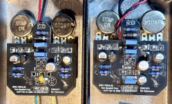
This Week on the Breadboard: The EHX Ripped Speaker

It's one transistor footprint to rule them all (Lord of the Footprints). The worst case is a bit of twister with some weird pin-outs on TH. Before, I'd have to have different footprints for EBC, CBE, DGS, DSG.. and even those would cause confusion at times. Now, it's just one with different labels for JFET vs BJT.

It covers SMD and TH and I think it's pretty clear which pad is what. I default to SMD transistors where I can. They're cheaper, and there are a few SMD-only options out there which are interesting.

View attachment 124097
It's a better option when it comes to DSG to alternative DGS transistor pinout, less chance of pins hitting each other.
The 2n2222 has different pinout depending on the supplier.
I see the advantage when doing Eyelet board builds!
 
That’s true, and I think AionFX has the best footprint in that format for SMD/TH. The problem is that when you solder SMD on there, it fills the TH pad which makes it harder to drop a pin in there for testing.
 
Nice treatise. And FWIW, I found a much simpler/smaller torn speaker-like circuit using a TL431 reference diode as the heart of the fart.
(If this sort of supplanting is not encouraged in these TWOTB threads, just LMK and I'll remove it.)

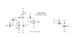
Slarty-Bartfast_TL431_Fuzz_Schematic.png
 
I found a much simpler/smaller torn speaker-like circuit using a TL431 reference diode as the heart of the fart.
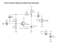
For Chuck and others who might try this - looks like a 2N3904 was added at some point as well as a cap change. Sounds like this version (below) is a louder, more usable fuzz at the expense of some Fart...? @Cybercow, maybe you can clarify. I somehow have a few TL431s, so I'll try both!

1789237692654.png
 
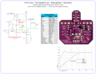
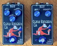
@rwl and I worked up a more populated version of the TL431 and have PCBs for it.
Ooh! Interested! Did you find the Tone control somewhat unnecessary or were you just trying different versions? Apologies Chuck, Cyb started it!! Ha... Although this is a pretty cool diversion (and still very much in Fartland)... :)
 
Ooh! Interested! Did you find the Tone control somewhat unnecessary or were you just trying different versions? Apologies Chuck, Cyb started it!! Ha... Although this is a pretty cool diversion (and still very much in Fartland)... :)
Just trying variations on the theme. The added tone control mostly just plays with the bottom end.
 
Some questions on the Slarty Bartfast's Cat pedal circuit.

What is the TL431's cathode voltage?
How much does the cathode voltage change when changing R1-R3 by 10x?
The freq response plot shows 3 curves. How do those relate to the position of the TONE pot? What is the FUZZ pot setting for those curves?
 
Some questions on the Slarty Bartfast's Cat pedal circuit.

What is the TL431's cathode voltage?
How much does the cathode voltage change when changing R1-R3 by 10x?
The freq response plot shows 3 curves. How do those relate to the position of the TONE pot? What is the FUZZ pot setting for those curves?
Good questions all. I don't know off hand. But in order to appear as tho I can keep up with such heady questions, I'll open one up on the bench and put my meters to it and see what sort of hal-way intelligent responses I can come up with.

For starters, when the tone pot is used, basically the tips of the two left-most curves move back & forth between those two curves' positions. That curve trace was not of my making. Dunno what position the Fuzz pot was in. And I've no means of capturing curve traces from my handheld scope. :(
 
Last edited:
Some questions on the Slarty Bartfast's Cat pedal circuit.

What is the TL431's cathode voltage?
How much does the cathode voltage change when changing R1-R3 by 10x?
The freq response plot shows 3 curves. How do those relate to the position of the TONE pot? What is the FUZZ pot setting for those curves?
With a measured pedal supply input of +9.00vDC, the TL431 pin voltages are: C: 7.12v, A: 0.759v, Ref:3.24v
Next I'll pull those resistors and swap 'em for x10 values and get measurements.
 
Last edited:
Some questions on the Slarty Bartfast's Cat pedal circuit.

How much does the cathode voltage change when changing R1-R3 by 10x?
Virtually no change at all. Considering the TL431 is a reference diode, that makes sense. With R's 1, 2 & 3 at 10x their values: The measured pedal supply input of +9.00vDC, the TL431 pin voltages are: C: 7.10v, A: 0.789v, Ref:3.27v
 
With a 9.00V supply input, that puts Vcc at around 8.8V. Therefore, the voltage drop across R4 is 1.7V. 1.7V / 2.2K = 773μA anode current. A cathode voltage of 789mV across 1K says the cathode current is 789μA, plenty close to the measured anode current.

On my breadboard, I have:
R1 & R3 = 220K
R2 = 560K
C1 = 100nF
The TONE pot is a switch
C3 = 1uF (increasing to 10uF makes no diff.)
Q1 is omitted
The FUZZ pot is wired in parallel with R5 (C4+ to pin 2, pin 1 to GND), which increases the current thru the TL431.
All other components match your sch.

My measured voltages:
Vcc = 8.70V
Cathode = 6.04V
Anode = 625mV
Ref = 3.12V (TL431 pin 1)
The measured Ref current is around 1.7μA, close to the datasheet nominal 2μA value.
Dividing the anode current by the parallel resistance of R5 and the Fuzz pot (524Ω) puts the anode current at 1.12mA. TI recommends running the TL431 at a minimum anode current of 1mA. This is just a guideline.
The TONE switch has most of it's effect when FUZZ is over 7 (2:00). Below noon, it does basically nothing.

Lotta gain, lotta headroom. When FUZZ is dimed, lotta harmonics 😁
 
Back
Top