This Week on the Breadboard: The 'lectric Mama Flanger

Chuck D. Bones

Circuit Wizard
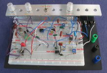
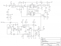
I wanted to build something using the recently acquired V3207D and MN3102 chips, so here's the first pedal out of the gate. It's a flanger based on the EHX Electric Mistress, with some updates and mods. I remember tracing an Electric Mistress back in '77. The design is both minimalist and clever. Unlike most clock oscillators, the one in the EM modulates the period of the clock rather that the frequency. That means that the pitch shift is constant across the entire sweep. The LFO in the EM was too clever for words. While it worked pretty well, it varied considerably from unit-to unit. I deployed a more traditional LFO, including clicking prevention. The freq range runs from 0.07Hz to 9.2Hz. At the low end of the speed range, it's a chorus. At the top end of the range, it sounds like a ring modulator. The tone is quite smooth, despite the minimal filtering. These V3207D's rock! I added a balance trim to achieve the deepest notches. I never had much use for the FILTER setting, but it does come in handy when adjusting the timmers. Next, I'm going to try a sinewave LFO to see how that sounds.

'lectric Mama breadboard 03.jpg


'lectric Mama v0.2.png
 
Thanks!

C2 should be film, Q1 & Q2 can be any high-gain Si.

Not shown:
  • Anti-pop resistor on the input.
  • Power protection and filtering. Use 100uF & 100nF for filtering.
  • Switching and On/Off LED.
 
Awesome Work, Chuck! How do you like the more chorusy sounds of it?
I might have found just the project for the couple of 3207 and 3102 I've recently gotten
 
I have tried a sinewave LFO and I find the results much more sonically satisfying. The issue now is making a sinewave LFO that is tunable over at least 2 decades, fairly low distortion and reliable. I have one on the breadboard, but it does not really meet any of the criteria. I ran across a paper by noted Caltech professor Dr. R. D. Middlebrook that offers a solution. Once I get that working, I'll post an updated schematic.
 
I have tried a sinewave LFO and I find the results much more sonically satisfying. The issue now is making a sinewave LFO that is tunable over at least 2 decades, fairly low distortion and reliable. I have one on the breadboard, but it does not really meet any of the criteria. I ran across a paper by noted Caltech professor Dr. R. D. Middlebrook that offers a solution. Once I get that working, I'll post an updated schematic.
It gets really serious when Chuck checks out what another genius has to say... I'm twiddling thumbs and trying to grow new neuron connections in anticipation. ;)
 
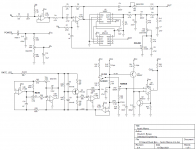
Here's the latest version. Took a bit of fiddling to get the sinewave LFO working, but it's working very well now. This is not an easy build because for optimum performance, the four trimmers have to be adjusted using a scope and sig gen. But you can get pretty close tuning them by ear. U4 should be a rail-to-rail opamp. A pair of CA3130s will work nicely. The LT1490 I used is a great dual opamp, but it's a little pricy at over $5 ea. This circuit can be made to work with a TL072 for U4, but the sweep range is diminished. This circuit is picky about which JFET you use for Q3, and whatever JFET is used requires three resistors to be selected-in-test (SIT). We want Q3 to have Vp between 1V and 2.5V (more is better) and Idss has to be less than 10mA. R31 & R32 are calculated based on Vp and Idss. R33's value depends on Q3's parameters and is chosen to get the maximum sinewave signal at U4-7 without clipping. As my mentor Arpad used to say "If it's do-able, somebody vill do it!"* If this Rolls-Royce version is a bit too much, then Q3, R29-R31 and D2-D3 could be replaced with four diodes and sound pretty much the same. No SITs and no TR4.

'lectric Mama v0.4.png


* The implication was that just because a thing could be done, that didn't mean it should be done.
 
Seemingly legendary resources by Dr. Middlebrook if anyone else is interested.
Have me questioning if I actually know how to read 😅

 
Back
Top