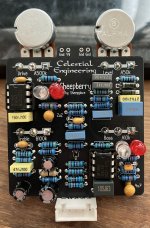
I'll have to look into the elaborate way you have changed the treble control. It's all a bit over my head - I addressed the mid-hump at the bass control in my Strawberry but your solution is no doubt more elegant and electronic. In the Strawberry I think I put the treble control on the equivalent of C12 in this circuit. I'm sure yours works better. Sigh... it's usually the case! Bloody experts.
Which do you like better - the Strawberry or the Lingonberry?
Here's a little insight into my process.
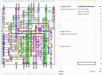
I use VeroRoute to lay out the board. It keeps track of all of the connections for me.
I export the Vero image to a PNG file, import it into Paintshop Pro and set the background color to transparent.
Then I drop the image onto an Excel sheet, with the rows and columns sized to make a nice grid.
After that, I type a big red X into each cell where I want a cut. Sometimes I add extra cuts to improve the isolation between strips.
I add the row and column markers and mark all of the I/O connections.
Excel counts the X's so I get a total count of cuts.
I manually fill in the number of links on each row, then Excel counts those up. That's how I get the picture above.
Than I make a copy (screen grab) of the component side layout and mirror it so I have a Cu side layout.
I use the Cu side layout as a guide for marking the actual Vero for cuts (drilling). I check that a couple of times and then drill the board on a drill press.
Next, I visually inspect the board to make sure the cuts are all good and remove any swarf with an Exacto blade. Then I check it for shorts with a DMM.
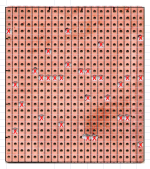
After that, I scan the Cu side board, import the image into Excel and overlay the drill guide to verify I made all of the cuts in the right places. You can see where I got a little bit sloppy with one of the holes
After that, I clean the board with IPA and start assembly.
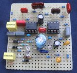
Jumpers go in first, then IC sockets. Solder & inspect. Sockets & jumpers make good landmarks.
Then the resistors are installed. Solder & inspect.
Axial diodes go in next. Solder & inspect.
Next any metal can parts and trimpots. (none in this build).
Film, MLCC & SM caps. Solder & inspect.
Tantalum caps. Solder & inspect.
LEDs. Solder & inspect.
Aluminum caps. Solder & inspect.
Once board assy is complete, I clean the board and inspect it once more. Any remaining shorts, misplaced components or weak solder joints are cleaned up.
Notice that parts which are easily damaged by an errant soldering iron go in towards the end.
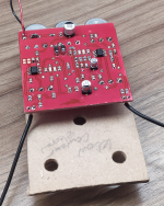
Mine is finally in the box, juicy. Full of vintamins, those berries
But really, very versatile drive from mild OD to distortion territory. Efficient tone controls: tick.
Nice with the comp control, I live more on the below noon more headroom end after initial playing.
Opamp ate TLC2272 and NE5532.
That's what happens as I have been waiting for a big lot of UV printed enclosures that have finally arrived a few days ago while I had a bunch of pcbs already mostly populated.
More to come in time...
My mum always said to me "Son, if you're going to have asymmetrical clipping by having different Vf between diodes you might as well go all the way". She was a wise woman, my mum.