Chuck D. Bones
Circuit Wizard
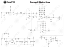
A strange and interesting Dirt Box. Here's the stock schematic. The most interesting part is the parallel distortion path thru IC2.1. This is a bandpass filter centered near 55Hz with 36dB gain and a Q around 4. D3 and D4 provide limiting, but they also complicate the filtering. Their leakage can affect the filter tuning and when they start conducting, the filter freq moves around. The common lore is that MXR is replicating the resonance in a Marshall speaker cab. The effect that we get is an audible thump when RESONANCE is turned up and we pluck the bottom strings. This is all pretty cool, but what if we made the filter switchable? I replaced C6 & C8 with 6 caps and an on-off-on DPDT toggle switch. Now the filter can be tuned to 55Hz (Classic), 120Hz (Heavy) or 750Hz (Mid Boost). Classic gives us the speaker cab resonance, Heavy gives us a prominent Bass boost, and Mid Boost makes for a stuck wah midrange honk à la Michael Schenker.
These are my mods:
1. Omit the charge pump. I can run it on 18V if I like, but it sounds great running on 9V.
2. Increase R101 to 12K to make the opamp clipping in the 2nd stage more symmetric.
3. Jumper C10. No need to block DC here. The voltage is the same on both sides of C10.
4. Change C5 to 1uF film. 1uF is more than enough capacitance here.
5. Change C3 and C7 to 47pF, which are more common.
6. Change the DRIVE pot to C50K for a smoother feel.
7. Change the FILTER pot to C250K and change C13 to 1.5nF. The FILTER knob range is now more usable.
8. Change C11 to 4.7nF and R14 to 10K. This pedal was way too dark for my tastes. The FILTER knob can still make it plenty dark. If you want to go darker still, increase the FILTER pot to C500K.
9. And the Pièce de Résistance: replace C6 & C8 with a DPDT on-off-on switch and three pairs of capacitors: 2.2nF, 15nF & 33nF. I also changed the RESONANCE pot to B10K so that the filter freq changes less when the RESONANCE knob is turned.
These mods are all optional and can be used in any combination.

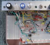
I re-arranged the IC pairing on the breadboard for better flow. The first two stages are at the upper right. The clipping and filter stages are top center (the TL072 is hiding under a large 2.2nF SM cap). Last two stages are bottom center.
Knobs: VOLUME - FILTER - RESONANCE - DRIVE - Res Filter Sw.

These are my mods:
1. Omit the charge pump. I can run it on 18V if I like, but it sounds great running on 9V.
2. Increase R101 to 12K to make the opamp clipping in the 2nd stage more symmetric.
3. Jumper C10. No need to block DC here. The voltage is the same on both sides of C10.
4. Change C5 to 1uF film. 1uF is more than enough capacitance here.
5. Change C3 and C7 to 47pF, which are more common.
6. Change the DRIVE pot to C50K for a smoother feel.
7. Change the FILTER pot to C250K and change C13 to 1.5nF. The FILTER knob range is now more usable.
8. Change C11 to 4.7nF and R14 to 10K. This pedal was way too dark for my tastes. The FILTER knob can still make it plenty dark. If you want to go darker still, increase the FILTER pot to C500K.
9. And the Pièce de Résistance: replace C6 & C8 with a DPDT on-off-on switch and three pairs of capacitors: 2.2nF, 15nF & 33nF. I also changed the RESONANCE pot to B10K so that the filter freq changes less when the RESONANCE knob is turned.
These mods are all optional and can be used in any combination.
I re-arranged the IC pairing on the breadboard for better flow. The first two stages are at the upper right. The clipping and filter stages are top center (the TL072 is hiding under a large 2.2nF SM cap). Last two stages are bottom center.
Knobs: VOLUME - FILTER - RESONANCE - DRIVE - Res Filter Sw.
Last edited: