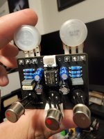
Tonevendor MKII no signal

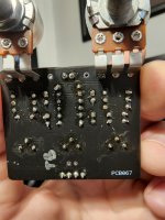
I cannot for the life of me figure out why, but I built a Tonevendor MKII and have no effect signal (using PedalPCB test rig). I have signal in bypass, LED power, and voltages on all transistors appear to be correct. Is there any reason the test rig doesn't work when using charge pumps to switch to positive ground for PNP effects (i/o jack tips aren't at - 9V because of the way the test board circuit is laid out)? I've built a ton of pedals and never had this issue. Super simple circuit, it's driving me nuts. I tried switching out transistors too, no luck there either. No solder bridges, all transistors have the correct pinouts. Any thoughts are appreciated! 20220811_062151.jpg
 
Last edited:
The PedalPCB test rig (Auditorium). That's why I'm curious, since this uses the charge pump to get positive ground, I'm wondering if it won't work with the Auditorium (not sure if the jacks get their ground referenced to the PCB ground when not in bypass or if it always stays at the incoming center negative ground)
 
It should work like any other negative ground effect, that's the point of the charge pump.

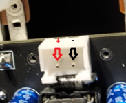
As long as the +/- pads are connected at the top you don't have to connect any of the other grounds with the Auditorium. It won't cause a problem if you do, it's just not necessary.

You say you have LED power, does the LED light when the circuit is active?
 
I guess the power ground reference never actually changes now that I think about it, the LED runs off negative ground too. Might as well wire up some jacks and see if that's the issue lol
 
It should work like any other negative ground effect, that's the point of the charge pump.

As long as the +/- pads are connected at the top you don't have to connect any of the other grounds with the Auditorium. It won't cause a problem if you do, it's just not necessary.

You say you have LED power, does the LED light when the circuit is active?
I have signal in bypass, LED power, and voltages on all transistors appear to be correct
 
Yes, the charge pump generates a negative voltage (with respect to ground) so ground remains at a daisy-chain friendly 0V.


You aren't by any chance connecting the IN/GND/SW/OUT wires backwards to the Auditorium, are you?

I ask because it's easy to do, I've done it several times myself.
 
Also just to be sure, the power is still connected as usual to this PCB. The polarity should not be reversed.

1660218053061.png


There's no reason it shouldn't work on the Auditorium like any other effect.
 
Nope, it functions no different from any other effect. The IN/OUT jack sleeves are still at 0V GND like always.

It's technically "positive ground" with respect to the rest of the fuzz circuit because the circuit is running on -9V. 0 is more positive than -9.

But to anything external to the circuit (other pedals, jacks, etc) ground is at the usual 0V potential.
Yeah this makes sense, the supply voltage is all that changes. I have no idea what to make of this lol
 
So I came home from work and just wired everything up including all of the jacks (the benefit to using the headers for the switch and 9V supply) and it works great. Now I need to see if I have an issue with the 3pdt on my Auditorium...
 
Back
Top