Trimpot Adjustment - Son of Ben

Vp is the same as Vgs(off). With N-channel devices, Vgs(off) is always a negative number. Since that's understood, we frequently refer to Vp and leave off the minus sign.

Your Peak Atlas is not measuring/reporting Vgs(off) correctly. Vgs(off) is usually specified for Id << 1uA. In the datasheet above, it's specified at Id = 10nA.
Thanks. I may be able to change the setting, I'll look into it next time I boot up Windows. I'm mostly a Linux user but the Peak Atlas software only runs on Windows. It's entirely possible that I've messed up the settings, since I don't really know what I'm looking at all I can do is measure known good examples and compare the numbers.
 
It's also possible that there are typos in your reported data. You report Idss = 0.43mA. Idss is the maximum current that the JFET can flow, it can't get any higher except in a fault condition. Then you report Rds(on) at Id = 1.2mA. They can't both be correct.
 
It's also possible that there are typos in your reported data. You report Idss = 0.43mA. Idss is the maximum current that the JFET can flow, it can't get any higher except in a fault condition. Then you report Rds(on) at Id = 1.2mA. They can't both be correct.
It's copied directly from the Peak Atlas software, so it can't be a typo.

I'm using Windows now, so here's a screenshot (and graphs) of the same J201.

I haven't tried this particular J201 in a circuit, but I have similar results from others that do work.

Here are the results for the J201s that are in my SoB pedal, which works.

J201 Ben R
Vgs(off)=-0.61V at Id=5.2µA
Vgs(on)=0.40V at Id=1.20mA
gfs=1.9mA/V at Id=0.7mA to 1.2mA
Idss=0.49mA at Vds=2.99V
Rds(on)=592.6Ω at Id=1.2mA and Vgs=0.0V

J201 Ben C
Vgs(off)=-0.70V at Id=4.8µA
Vgs(on)=0.41V at Id=1.33mA
gfs=1.9mA/V at Id=0.8mA to 1.3mA
Idss=0.60mA at Vds=2.99V
Rds(on)=601.8Ω at Id=1.3mA and Vgs=0.0V

J201 Ben L
Vgs(off)=-0.72V at Id=5.3µA
Vgs(on)=0.39V at Id=1.35mA
gfs=2.0mA/V at Id=0.8mA to 1.4mA
Idss=0.62mA at Vds=2.99V
Rds(on)=583.9Ω at Id=1.4mA and Vgs=0.0V

Again, these are copied directly from the Peak Atlas software, I'm not typing anything so there's no typos.

EDIT: I stuck the same JFET in my LCR T7, and it says: Id= 0.23mA @Vg=164mV.
 

Attachments

  • scr01.png
    scr01.png
    34.8 KB · Views: 12
  • GRA1.png
    GRA1.png
    43.4 KB · Views: 12
  • GRA2.png
    GRA2.png
    37.7 KB · Views: 12
Last edited:
I can't make sense of those curves. They contradict the manufacturer's datasheet. JFETs are depletion-mode devices, which means that when Vgs = 0V, they are fully ON and by applying a negative Vgs, they gradually turn off. Vgs(off) and Idss are boundary conditions. The JFET operates in a linear region when Vgs is between 0V and Vgs(off) and when Id is between 0 and Idss. I attached the datasheet. Compare the bottom right graph on page 2 with your GRA1.png plot. Compare the upper left graph on page three with your GRA2.png plot. Note that they are not even close. I don't own a DCA Pro, I do not know how the displays are calibrated. What's an LCR T7?
 

Attachments

  • J201-J202 - Fairchild.pdf
    851.6 KB · Views: 7
LCR T7. TL;DR - cheap multi tester thing. Works pretty well as far as I can tell.

The DCA75 is kind of a mystery to me, too. I got a good deal on it when I had some money to blow, and felt optimistic about my ability to understand electronics properly. The manual doesn't help much. It's possible I have messed up the settings, but I couldn't find any way of adjusting them so I can't see how I'd have done it.

So, all it's useful for to me is, as I said, comparing the numbers to known good transistors. I know that the crap out-of spec 5457s I have give very different results to the good ones, so it does seem to do something accurately.
 
LCR T7. TL;DR - cheap multi tester thing. Works pretty well as far as I can tell.
I bought one of these and also built the kit I got off Ebay. Both are great for mundane measuring chores, (diodes, caps, resistors). Neither are very consistent in recognizing transistors. Like it only works 50% of time. 99% of what's being discussed in this thread is way over my head anyway.......:)
 
I bought one of these and also built the kit I got off Ebay. Both are great for mundane measuring chores, (diodes, caps, resistors). Neither are very consistent in recognizing transistors. Like it only works 50% of time. 99% of what's being discussed in this thread is way over my head anyway.......:)
Mine is useful for BJTs, in that it gives an hFE number that's simple enough for me to grasp and is very close to the DCA75 result.

It's the JFETs that are confusing. I have no idea what they're meant to do and reading about them does not help. I'd get more information from looking at runes.
 
I just ran it through again with that method, Chuck.
View attachment 1438
I dialed it in to exactly 1.67k. Boy oh boy does it sound great now! Trim 1 is interesting. It goes from no sound to a broken crackling starved voltage sound to perfection. I can see it being tricky for people. Thanks for the excellent method.
Just made this pedal and it was my first time doing a bias adjustment. This pic and thread helped me out big time!

Ryan
 
I'm learning as I go, Chuck. The Wolves are pure analog, baby.

Thank you, M6K.
This is only my third build (not counting my failed Echo Nightmare), and I am definitely a newbie when it comes to metering and such, so I'm basically trying to learn it all at the same. But that's how I thought the process was supposed to go.
HOWEVER..
Here's the thing. Well, two things.
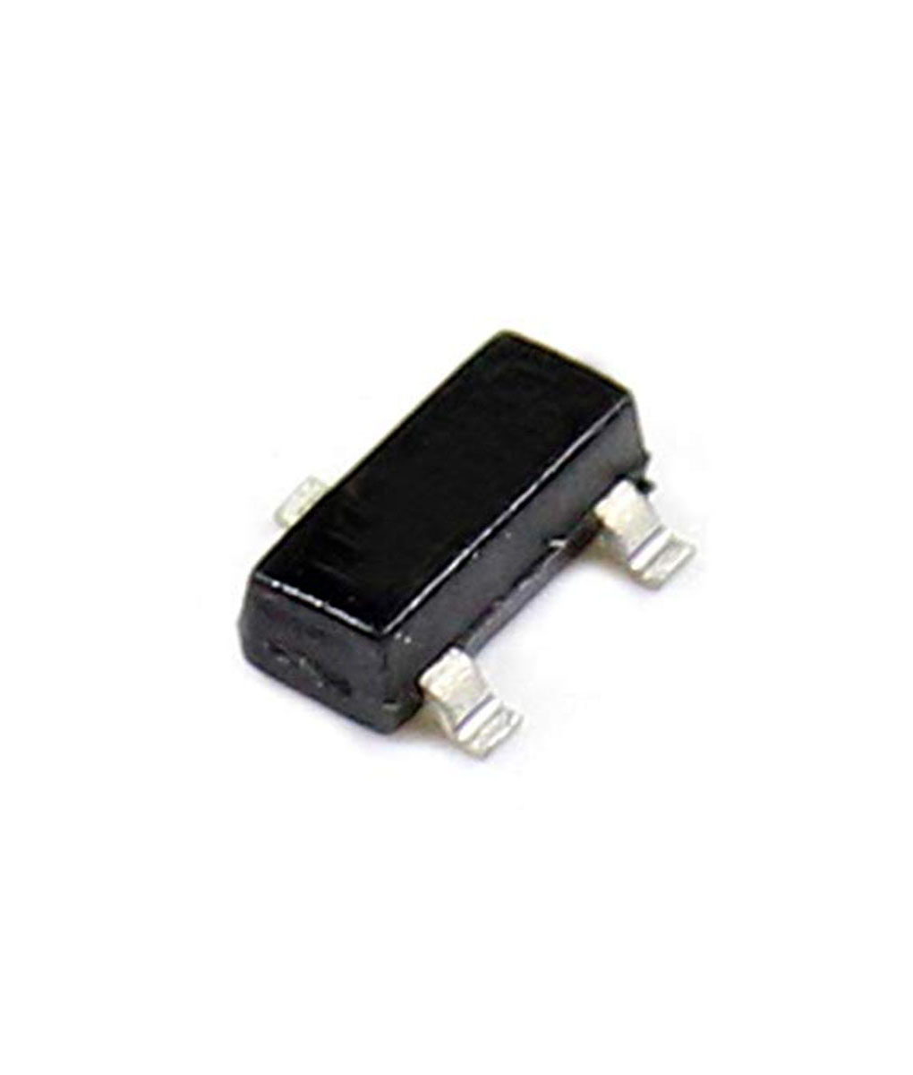
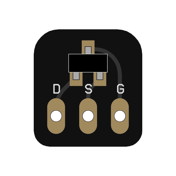
1) According to the datasheet of the installed "InterFet J201" the pins go 1) source, 2) drain 3) gate.(https://www.mouser.com/ProductDetail/InterFET/J201?qs=/ha2pyFaduh6EYvyYo4gV6ZjdGsoMaCrkP1C2KUJ4mQ=)

2) Unfortunately, that doesn't seem to matter because when I do as you so awesomely illustrated, (Meter set to 20 volts) I get no reading at all from any pin. Nada, zilch. Be it plugged in and (true) bypassed , plugged in and on. Unplugged...I just get nuthin'.
If it's plugged in and bypassed & I put the ground on the "source" (1) and the other on the drain (2) I get a reading that I can dial to "4." I have no idea if that is actually 4v or if it's just teasing me.

The pedal works and sounds pretty good. . But of course, if I can reach for the ULTIMATE TONE, man... I'd like to.
Interestingly, with the drive all the way down, I get no sound at all even with the volume cranked. I don't think that's supposed to happen.
I'm about to begin this build, and also purchase the same Interfet J201's from Mouser. I also see that the pinout is different on the Interfet's from what is apparently "typical".

Did these Interfet J201's still work OK for you? Or should I look to buy different ones?
 
Keep in mind that drain & source are interchangeable on JFETs. That explains the "different" pinout on the InterFET parts.

$3.58 ea is pretty steep for J201s. InterFET is milking the market for all its worth. OnSemi makes J201's in an SMD package for a fraction of what InterFET charges. Mouser carries them both, although the OnSemi MMBF201s are backordered 'til Jan. With Mouser you know you're getting legit parts.
additional options


I’ve got to be honest in that I don’t really understand the biasing of the trimpots (first time for everything!).

Good news is that the pedal is functional, and sounds pretty good to my ears, so perhaps no action is good action here.

I have a DMM, and I place the black probe to ground (in one of the enclosure screw holes), and touch the red probe to the D leg of the J201 (sourced from GuitarPCB). I’m getting voltage readings in the ~0.35 range, so I’m guessing I’m reading/doing this wrong. When I turn the trimpots, I don’t see much change in the reading. IMG_6365.jpeg

So, a few questions:

Power should be on or off to the pedal?
If power on, pedal should be engaged or no?
 
Last edited:
I’ve got to be honest in that I don’t really understand the biasing of the trimpots (first time for everything!).

Good news is that the pedal is functional, and sounds pretty good to my ears, so perhaps no action is good action here.

I have a DMM, and I place the black probe to ground (in one of the enclosure screw holes), and touch the red probe to the D leg of the J201 (sourced from GuitarPCB). I’m getting voltage readings in the ~0.35 range, so I’m guessing I’m reading/doing this wrong. When I turn the trimpots, I don’t see much change in the reading. View attachment 59576

So, a few questions:

Power should be on or off to the pedal?
If power on, pedal should be engaged or no?
0.35V seems too low for a functioning circuit, maybe you are reading the wrong pin?
 
Back
Top