Trimpot Adjustment - Son of Ben

I just went for it and it worked out ok. But feel free to post your pictures still as a resource to others who might need it!
Great to hear!

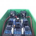
For anyone else curious, here's a guide on how to socket the SMD J201s, using the SOT23 through hole adapters.
  1. Solder the SMD J201s to your SOT23 through hole adapter boards (not needed if you bought them pre-soldered)
  2. Solder angled headers* to the adapter boards - the longer pins go through the adapter board, sticking out on the front side (J201 side, in this case)
  3. After the headers are soldered to the adapter boards, cut off the excess length of the soldered pins
  4. Once that's good, solder to the main PCB (see last photo for orientation)

*angled header used was Tayda part A-199: https://www.taydaelectronics.com/40-pin-2-54-mm-angle-single-row-pin-header.html but any 2.54mm right angle single pin header will work
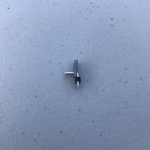
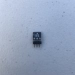
adapter board 1.jpg adapter board 2.jpg

adapter boards in the pedal.jpg
 
Great to hear!

For anyone else curious, here's a guide on how to socket the SMD J201s, using the SOT23 through hole adapters.
  1. Solder the SMD J201s to your SOT23 through hole adapter boards (not needed if you bought them pre-soldered)
  2. Solder angled headers* to the adapter boards - the longer pins go through the adapter board, sticking out on the front side (J201 side, in this case)
  3. After the headers are soldered to the adapter boards, cut off the excess length of the soldered pins
  4. Once that's good, solder to the main PCB (see last photo for orientation)

*angled header used was Tayda part A-199: https://www.taydaelectronics.com/40-pin-2-54-mm-angle-single-row-pin-header.html but any 2.54mm right angle single pin header will work


View attachment 5400 View attachment 5401

View attachment 5402
Nice and clean! I just used the cut legs from some electrolytics and made my own "headers" :) Next time I will be doing it your way because it is much cleaner and probably more durable. One question, will those header pins fit into a socket? I prefer to socket my jfets in case there is an issue I can easily swap them out without the desoldering hassle. That was the benefit to my method as the legs from the caps easily fit into the sockets.
 
Nice and clean! I just used the cut legs from some electrolytics and made my own "headers" :) Next time I will be doing it your way because it is much cleaner and probably more durable. One question, will those header pins fit into a socket? I prefer to socket my jfets in case there is an issue I can easily swap them out without the desoldering hassle. That was the benefit to my method as the legs from the caps easily fit into the sockets.
Thanks! I like your method too - resourceful (y)

The pins on the headers I used won't fit into SIP sockets. There are headers that do, but I've only found straight ones, not angled, before. For example: https://www.ebay.com/itm/Single-Row...757572?hash=item4641916204:g:rM4AAOSw37tWAUnp


s-l1600.jpg

You'd need angled ones to fit in the Son of Ben pedal. Angled ones exist but I'm not sure where they can be purchased.

If anyone else knows of a source for them, feel free to chime in :)

Update: it's possible to use the headers I linked in this post and carefully bend the long end to make them angled! Then they can be used just like the angled ones in my earlier guide, but with sockets.
 
Last edited:
Stupid question, but thought I would ask. To get close on TRIM1, I want to set it to 2K before I install it. Which side do I set to 2K? Do I measure from pin 1 to 2 or from pin 2 to 3?
 
Stupid question, but thought I would ask. To get close on TRIM1, I want to set it to 2K before I install it. Which side do I set to 2K? Do I measure from pin 1 to 2 or from pin 2 to 3?
Legs 1 & 2 are linked so adjust so Legs 2 & 3 in Red circles measure 2K prior to fitting :

Son of Ben 2K Pads.jpg
 
Ok. I finally got around to finishing this pedal and I have two more questions on biasing.

I got Trim 1 done. I used the method in this post where I connected Q1 drain to D1 cathode, and adjusted the trim until I got to 1.6k measured across R5. I am using 50k trimmers. I barely moved the trimmer to get vastly different values. Is this normal? If the actual resistance around this trimmer needed is around 2k, why specify a 50k trimmer? Why not a 5k and have more flexibility to dial it in?

The second question is for Q2 and Q3. I am getting ready to connect power and bias them. Do I need to have the foot switch and LED wired up as well? Right now the pedal is complete, but no LED, footswitch, or jacks have been connected. Can I leave those off until I have biased Q2 and Q3?
 
Good question about the trimmer. The 2K setting is just a starting point. Yes, the trimmer is touchy. There is a LOT of variation with J201s, so some people will need more adjustment range. Whether they'll ever need the full 50K is another question. My understanding is Benson does not put trimmers in the production pedals, they select the J201s.

You don't need the stomp switch, LED or IN/OUT jacks to set the bias. All you need is 9V power to the board.
 
My understanding is Benson does not put trimmers in the production pedals, they select the J201s.

Mine does actually have trimmers for both Q2 and Q3, but not Q1. And just as an additional data point, with 9.26V coming from the power supply, I read 3.85V in Q2's drain, and 3.89V in Q3's. Not very far off from the 4V recommended in the build doc. Q1's drain read 6.78V.
 
By the way, I just played my original Benson side by side with the Son of Ben after adjusting the trimmers in mine to match what I measured in the original, and they sound pretty damn close! Mine sounded a little flubbier until I pulled C10 out. Now they're head to head. Great job on this one @PedalPCB!
 
Two questions:
Does your original have C10?
Can you compare the Source voltages between OB & SOB on all three transistors?
 
building one of these in a few days

it sounds like maybe Q2 and Q3 require the 50K trimmers but perhaps Q1 could use a smaller trimmer to dial it in easier? I'm considering a 20K that I have
 
  • Like
Reactions: spi
@Chuck D. Bones my original doesn't have C10, no.

Here are the source voltages:

Benson:
Q1: 0.206V
Q2: 0.180V
Q3: 0.196V

SOB:
Q1: 0.130V
Q2: 0.184V
Q3: 0.122V
Just wanted to pass along some additional data here. The first set of J201s I used I could get biased above 3.8v on the drain. I bought that set from Pedal Parts Plus probably 5 years ago. I ended up using some that I bought from Guitarpcb that I was able to bias to exactly 4v, with a max of around 9v on the trimmer. Interestingly my source voltages were all higher. Q1 was around .3v, Q2 was .24v, and Q3 was .27v. The correctly biased set of J201s sounded substantially better, which makes sense. I'm guessing the first set were either fakes or just totally out of spec.
 
Back
Top