Troubleshooting help with Tuner.

BourbonAndGames

New member
Everything turns on, but not able to tune or get signal out. I can toggle the buffer modes and hear the relay clicking when switching from 1 to 2 or 1 to 3 and reverse, but no clicking from 2 to 3. Unsure if that is normal.

IC1 Pin 8 reads 8.58vdc to ground.
IC2 Pin 8 reads 5vdc to ground
IC3 and IC4 Pin 8 reads 8.67vdc to ground.
X1-5V pad reads 5vdc to ground.
The Green LED for charge flashes at the same interval, maybe a second in between each one?
Factory Reset and uploaded Firmware from the website as a just in case.

Did the build after awhile of not doing any plus using a new iron and without a good PCB holder. Eventually got it settled down mostly. I've checked component values and diode placement, but that doesn't mean I didn't miss it. I may de-solder the wires to the interface and re-do them as I'm not exactly happy with them but as far as I can tell they aren't an issue.

Thank ya!
Edit: I also used two different 9v power supplies, both rated 400mA+.


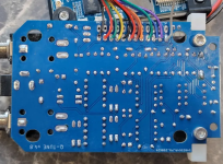
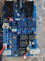
1777681725315.png 1777681785341.png
 
Everything turns on, but not able to tune or get signal out. I can toggle the buffer modes and hear the relay clicking when switching from 1 to 2 or 1 to 3 and reverse, but no clicking from 2 to 3. Unsure if that is normal.

IC1 Pin 8 reads 8.58vdc to ground.
IC2 Pin 8 reads 5vdc to ground
IC3 and IC4 Pin 8 reads 8.67vdc to ground.
X1-5V pad reads 5vdc to ground.
The Green LED for charge flashes at the same interval, maybe a second in between each one?
Factory Reset and uploaded Firmware from the website as a just in case.

Did the build after awhile of not doing any plus using a new iron and without a good PCB holder. Eventually got it settled down mostly. I've checked component values and diode placement, but that doesn't mean I didn't miss it. I may de-solder the wires to the interface and re-do them as I'm not exactly happy with them but as far as I can tell they aren't an issue.

Thank ya!
Edit: I also used two different 9v power supplies, both rated 400mA+.


View attachment 116439View attachment 116440
Huge apologies for missing this! I've been heads down on various projects. Are you still hitting issues? If so, let me know and we can walk through it together and get it working.

Edit: Your soldering looks great and those measurments look right too.
 
Last edited:
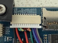
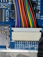
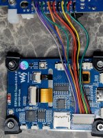
@BourbonAndGames Please take a picture of the back side of the screen. Specifically what I'd like to see is the JST connector. It looks like your wires are soldered correctly on the Q-Tune PCB, but I'd like to see the other side of those.

A common problem is that the JST connector isn't fully seated. WARNING: Don't just push it in. It's better to pull it out first and then check and double-check that the pins inside of the connector on the back of the board aren't bent. Once you've confirmed they're not bent, carefully slide in the connector the right way and fully insert it. Even I ran into this problem a few weeks ago and it burned a couple hours before I realized what I had done.

Here's a picture of what it should look like (ignore that I've chopped off the unused wires on this one). The black wire on the one end should line up with the GND pin on the back of the screen as shown.

IMG_9986.jpeg
 
No worries at all about the delay!

And yes, still an issue. I'm thinking of redoing the wires for the connections on the PCB side in case I broke some of the strands while stripping them.

The pins inside look perfectly straight. Deal with that style at work sometimes so I know they can be a right pain. I can try and use my magnifying glass to get a good picture of them if need be.
 

Attachments

  • 20260520_185011.jpg
    20260520_185011.jpg
    407.5 KB · Views: 6
  • 20260520_184943.jpg
    20260520_184943.jpg
    625.7 KB · Views: 6
Yeah, that looks great! There was one time I didn't solder in my GND wire well enough and it was causing issues, so it's likely one of the signal wires might need attention, specifically the GPIO15 wire.

Something you might try is to probe for the audio signal at various places in the circuit. Send in a sine wave with an audio generator or play some guitar on a looper and connect that to the input of Q-Tune. Then, with a probe hooked up to your guitar amp and an instrument cable (can literally be just a capacitor touching the tip of the instrument cable), you could carefully touch the capacitor to GPIO15 when in tuning mode and see if you're getting a signal there.

If you're not, you could trace it backwards from there looking at the input to the TL072 – though you have to be super careful not to short certain pins. Check with the schematic to verify test points.
 
Set my signal generator at 440hz sine wave and scope for 2ms/div and 50mV/div (think I set it up right.) I get 440hz at my input jack and went to IC5 Pins 7, 8 and 9 and I'm seeing 440hz on all three without changing state. I went to C1 to see what I'd get, was getting it bouncing around from 1.6khz to 2.5khz, same for IC1A Pin 3 and 1.

Hopefully won't be such a long delay by next time I post now I got enough free time to set everything back up on my desk.
 
A little odd that you’d see 440 Hz on Pin 7 of IC5 since that should be connected to GND. If you switch from standby to tuning mode, you should start to see a signal at C1. Does that happen? Or, if you go into Settings > Tuner > Bypass Type and select Buffered Bypass, you should also start seeing a signal at C1. Doing those couple of tests should make sure that your relays are properly working.
 
I need to find different probe for my scope that isn't just the hook. I can only touch the solder points on the back of the board for IC5/6, I'll partially unseat them tonight and try again that way plus look for my probe pack that came with my scope.
 
Back
Top