pbrommer
Well-known member
Good evening -
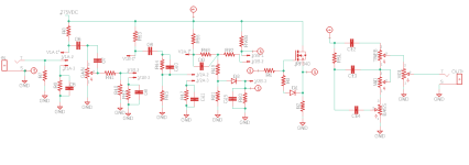
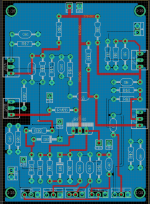
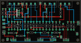
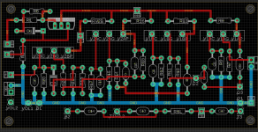
I like making perfboard layout of preamps, but I'm kind of nervous of the longevity of some of them (one is working, but the ground and +250VDC are literally millimeters apart!) . So, I've taken a shot at putting together a 125B sized (but no tubes!) layout for 2 tubes plus a (gasp) MOSFET CF option. There are many options and extra parts, just in case you want to build them out. If you would all kindly take a look and see. I can't see any major issues -- it's not the prettiest and balanced, but I think it will work. Let me know your thoughts. EagleCPB (I know, but I get it free at work!) and schematic are attached.


Couple notes:
1. There is a plate TS out and cathode follower TS out. This is due to some amps use plate driven tonestacks (Fender) and other use cathode followers (Marshall).
2. The +275VDC will come from a SMPS board.
Patrick
I like making perfboard layout of preamps, but I'm kind of nervous of the longevity of some of them (one is working, but the ground and +250VDC are literally millimeters apart!) . So, I've taken a shot at putting together a 125B sized (but no tubes!) layout for 2 tubes plus a (gasp) MOSFET CF option. There are many options and extra parts, just in case you want to build them out. If you would all kindly take a look and see. I can't see any major issues -- it's not the prettiest and balanced, but I think it will work. Let me know your thoughts. EagleCPB (I know, but I get it free at work!) and schematic are attached.


Couple notes:
1. There is a plate TS out and cathode follower TS out. This is due to some amps use plate driven tonestacks (Fender) and other use cathode followers (Marshall).
2. The +275VDC will come from a SMPS board.
Patrick


