Tube Town B-Flex

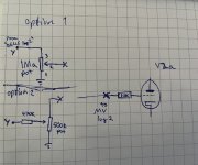
Looking closer at this I see two (of possibly several) options:

Option #1:
I like your original suggestion of replacing R14 and R15 with a 1m pot. It changes the circuit very little and gives the volume control you desire. I would use an audio taper pot.
This gives the widest range of volume control, possibly overdriving the PI (edit: and/or Power Tubes) at higher settings.

Option #2 would be the top schematic. This retains R14 as R5 (top 470k) and replaces R15 with a 1m (VR4) pot in parallel with a 1m (R7) resistor. The resistor in parallel with the pot gives an overall resistance of 500k ohms. Placing a fixed resistor in parallel with a linear taper pot is a method of creating an "audio taper like" pot when an audio taper pot is not available. (The fixed 1m resistor and 1m pot could be replaced with an audio taper 500k pot with the same result.) This would give a volume range that maxes at the same fixed volume as the original TT B-Flex.
 
Last edited:
IMG_8789.jpeg

10K gridstopper for V2a aka gainstage before splitload PI stage.

@GAStan cathodyne splitter there so unity gain at most and poor resistance for blocking distortion.

I’d try option 1 first to see what are V2a+b limits with signal level.

Edit. That’s NOT cathodyne phase splitter. Early long tail pair or what the heck? Or is it some iteration of paraphase?
 
Last edited:
Ok, let's try Option 1 and see if the overdriven V2a+b sound musicals. If not I'll go for option 2.

Ok for the grid stopper on V2a, but why not on V2b also ?
I also notice there are no grid stopper on V1a and V1b. Could this be an good enhancement to add grid stopper here too ? My room is probably not RFI/HFI free..
What kind of resistors should grid stopper be (power wise) - 1/2W ? 1W ? More ?

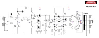
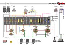
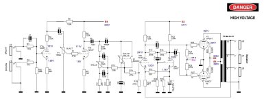
I repost the schematic and the layout here to avoid switching back to page 1 :
Schematic.jpg
bflex-layout_page-0002.jpg

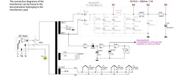
I have another question, there is an unused 5V supply in the PT. Can I use it to light LEDs inside the enclosure ?
PSU schematic.jpg
 
Last edited:
0.5-1W is all ok. The amps I have worked with have had 0.25-0.5W grid stoppers even on power tubes. I use bigger wattage ones as they’re sturdier for floating connections and have longer leads.

Btw I looked PI on latest schematic you posted and it’s not split-load PI, but grid stopper is still beneficial at v2a as it makes a long run from previous plate/stage.
 
It may be a paraphrase inverter as I found someone who made some modifications in a that amp years ago mentioning it :

Quote :
"Hi,
I made a bflex for my bass player a few months ago. It was working fine but, even if I added a line out, it was good for practice, but too weak for the rehearsals with our heavy rock Drummer.
So he asked me if I could upgrade it to 100 Watts.
Here's what I did :
- Replaced PWT and OT with your Soldano 100 Watts ones.
- replaced the 2x6V6 by 4x6L6GC
- Replaced the PI Tube with a ECC82
- Added a Hammond 159Q choke.
- Kept the TT PSU mini CT, but added 2x220 MF for B1 (so I have 210 MF for B1)
- Added 2x2 UF5408 before the D1 and D2 of the PSU.
- Added a Standby just before B1, So the 210 MF are charged First.
- Fuses of 4AT AC Input, and 2AT HT
- R6PSU is now 22 K
- Screen resistors = 470 Ohms 5W
- Grid stoppers = 10k
- NFB Resistor = 47 K on the 16 Ohm Tap
- R19 of the Paraphase invertor is now 517 K to minimize the unbalance (still unbalanced though)
- Bias taken on the 60V tap of the PWT, R101 is now 4.7K
- B1=480V, B2=477V, B3=361 V, B4=351 V Bias -53V
- 6L6GC Biased at 40 mA (I installed 1 Ohm resistor on the Cathodes)
-> for 1 Khz sinus input, I got 110 Watt RMS under 8 ohms

The amp so far is working great, very powerfull on 4 ohms with two Ampeg cabinets 1x15."


@JohnnyCreepy : Note that the guy did add grid stoppers of 10k, without saying exactly where, just like you recommend.

EDIT : I have an answer : they use shielded cables between input jacks and V1a, so I suposed a grid stopper resistor can be avoided. About V1b, a grid stopper can alter the tone here (or at least reinforce the mid, which might be a good thing for a bass amp - but I'll start without it and figure out later). So I'll rely on your knowledge and just add one in front of V2a.
 
Last edited:
I have another question, there is an unused 5V supply in the PT. Can I use it to light LEDs inside the enclosure
Didn’t notice this earlier, but if you want to pollute your signal with noise go for it! With careful planning it’s doable, but there’s a reason why chassis lights are rare. Gigging people have problems with stage lights etc. My 100w amp picks ticking noise from slightly worn light ballasts few meters away so I play my rehearsals without lights. :D

Note that the guy did add grid stoppers of 10k, without saying exactly where, just like you recommend.
He is talking about power tube stoppers there. Grid stoppers reduce blocking distortion, oscillations and RF interference. Preamp grid stoppers can be anything between couple kilo ohms to hundreds. These grid resistors should be placed right into tube socket grid pin lugs with as short lead as possible on lug side. Most designs get away placing ’em further than socket lug, but it’s a thing to rule out if having some problems on an amplifier with unsteady operation.

I’m getting a copy of 1953 RCAs ”bible” cookbook for AF/RF circuit design soon and gonna quote things from there for sure. It doesn’t cover people gonna be playing square waves through tube amp, but still it’s covering most of things we’re looking here. :)
 
Ok, no lights when I'll start the damn thing. I got it. :LOL:

I think now I have all my answers. Time has come to order.. One last thing : I will opt for a switchable 1Mohm log MV pot to include a bright cap. 100pF seems a good value to start (good effectiveness for bass frequencies ? ceramic disc cap ?)

I really want to thank you all for the time you spent answering my noob questions. And for all the documentation. The LenardAudio website turned out to be very informative.
 
Last edited:
Ok, no lights when I'll start the damn thing. I got it. :LOL:

I think now I have all my answers. Time has come to order.. One last thing : I will opt for a switchable 1Mohm log MV pot to include a bright cap. 100pF seems a good value to start (good effectiveness for bass frequencies ? ceramic disc cap ?)

I really want to thank you all for the time you spent answering my noob questions. And for all the documentation. The LenardAudio website turned out to be very informative.
You have good questions here! Not too hard and all the tube related & time consuming reading sessions finally find use. I’m def a noob too when calculus is involved and still learning with a long road ahead.

I have 3 amps on my bench atm. One is mostly done, but needs time for troubleshooting session about loss of signal. Second is gutted and PCB just got populated, but gonna get remake after I get it together working and decide what to build on it. Third one is partly build, but some parts are not soldered yet, power transformer is unconnected and some wiring is missing.

For all-purpose-try-this-out-caps buy a box of 1-2kV multilayer ceramics from ebay, aliexpress or similar. You get pF to nF range caps to play with for 10-20 coins! When the right value is set, replace it with higher end poly cap (f.ex. Wima) for reducing microphonic effect what ceramics tend to have on circuits prone to pick vibrations.
 
I'm actually going to order a set of ceramic capacitors from Amazon. I'll run some tests.

I couldn't help but look into how to add a pair of 6V6GT in addition to the one already there. It doesn't seem that complicated (as long as the transformers can handle it); it's almost a copy-and-paste of the original power stage.
Maybe that’ll be the next modification in 2027. But for now, let's try to make this thing play music when we need it to and stay quiet the rest of the time.

Good luck with your three ongoing projects!
 
Last edited:
Adding a pair of power tubes means new OT and possibly a new PT. So that's not something to do on a whim fyi.
 
Adding a pair of power tubes means new OT and possibly a new PT. So that's not something to do on a whim fyi.
Sure ! That's why I said "as long as the transformers can handle it" which means I will check if they can if/when I decide to boost this little amp.
 
Hello, everyone!
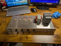
I received the kit from Tube Town, Germany, along with the various parts I needed to make the modifications I wanted.
As is often the case with purchases from Germany, everything arrived, no mistake, well-packaged, clearly labeled, and well-documented.

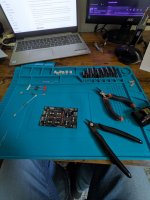
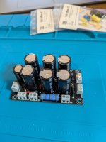
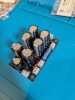
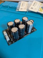
I started the build with the Power Supply Unit :
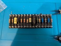
PXL_20261101_151837948.jpg PXL_20261102_130624161.jpg PXL_20261102_130644441.jpg

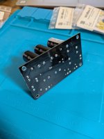
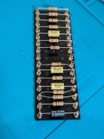
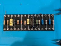
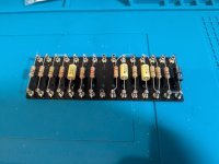
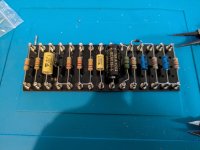
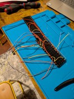
Then I continued assembling the turret boards:
PXL_20261102_130723012.jpg PXL_20261102_151202761.jpg PXL_20261103_185500234.jpg

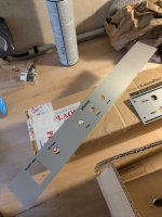
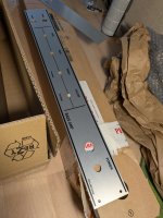
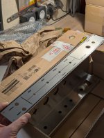
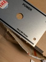
Next, I installed the faceplate and rearplate that I had custom-made in Sweden.
PXL_20261030_141622393.jpg PXL_20261030_141632208.jpg PXL_20261030_141712958.jpg

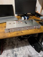
I mounted them on the chassis, then fitted the chassis with the potentiometers, jacks, fuse box, etc....
PXL_20261102_174732559.jpg
At this point, I had planned the locations of the measurement points for bias adjustment as well as the position of the bias adjustment potentiometer.

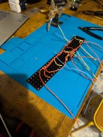
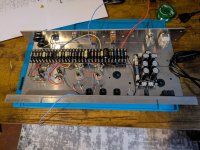
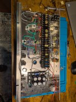
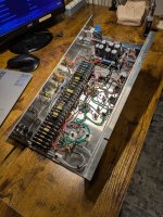
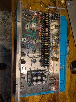
I then secured the turret boards to the chassis and began connecting the various components:
PXL_20261104_153935445.jpg PXL_20261105_175312522.jpg

Last but not least, the transformers :
PXL_20261106_173739444.jpg PXL_20261106_173812922.jpg

I then checked everything three times. And I plugged it in first without the valves. The supply voltages were correct.
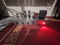
Next, I connected the tubes and adjusted the bias based on measurements taken on my 1-ohm resistors.

PXL_20261107_180835123.jpg

To my surprise, the overall volume is very shy. I plugged in a passive P-Bass with Lollar pickups. With the gain and volume turned all the way up, the volume is still pretty low for an 18W amp.

So I decided to run it through my Nobelium preamp, and I was finally able to get a decent volume, close to what my Fender Rumble 40W amp sounds like at 50% volume.

The best part: this amp is incredibly quiet. No noise, no interference. The sound is warm (supposedly close to that of an Ampeg Portaflex) and very similar to my solid state Ampeg Micro VR, with that typical tube-like roundness on top of it.

After enjoying the amp for a few hours and getting familiar with the various controls, I measured the voltages of the different B+ supplies and everything was ok, except the voltage of the phase invertor.
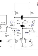
The amp uses a “paraphase invertor” circuit, and the anode voltages of the two tubes are very unbalanced. According to the amp’s documentation, I should have 241V and 220V, but I measured 300V and 200V.
I'm wondering if I can balance this out using resistors R17 and R19, which form a voltage divider bridge...
Is there a paraphase inverter specialist among you?

I'm reposting the diagram of the phase-inverter stage here:
B-Flex .jpg Schematic.jpg
 

Attachments

  • PXL_20261030_141644415.jpg
    PXL_20261030_141644415.jpg
    331.2 KB · Views: 8
  • PXL_20261105_175310509.jpg
    PXL_20261105_175310509.jpg
    610 KB · Views: 2
  • PXL_20261103_185450406.jpg
    PXL_20261103_185450406.jpg
    443.6 KB · Views: 2
  • PXL_20261102_130616184.jpg
    PXL_20261102_130616184.jpg
    282.7 KB · Views: 2
  • PXL_20261102_130633183.jpg
    PXL_20261102_130633183.jpg
    237.9 KB · Views: 1
  • PXL_20261102_130708916.jpg
    PXL_20261102_130708916.jpg
    239.2 KB · Views: 0
  • PXL_20261102_151143345.jpg
    PXL_20261102_151143345.jpg
    259 KB · Views: 1
  • PXL_20261102_151149054.jpg
    PXL_20261102_151149054.jpg
    258.8 KB · Views: 2
Last edited:
IMG_8876.jpeg
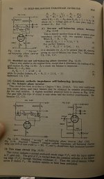
Haven’t messed with see-saw floating paraphases, but above is what the bible has to say of your PI. Balance is greater with fig.12.35 which drops R20 and jumpers C10.

BUT

I would start tube rolling. Change V1 and V2 positions to see if current V2 in use has really unbalanced halves. If voltages look better with other tube in V2 then good! But remember that anode voltage balance doesn’t exactly tell how close output balance is. If voltage balance doesn’t get better with tube rolling, then it’s wise to check if you have too much feedback. Go disconnecting feedback lead from OT secondary to see if there’s too negative feedback via R23 causing the loss of output. If output difference is great compared for stock circuit with FB, time to adjust R23 value.
 
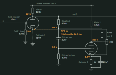
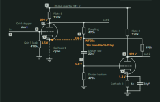
I just modelled your PI with my awesome tool ;) and I am getting V2a at 229V and V2b at 219V. It's not a perfect model, but I would be surprised if it were more than a few % off. It's also the best balance you can have with E12 values apparently. Are you sure you have the right resistors built in? And your grid leaks are properly grounded to an actual ground?

(Don't mind the imperfect wires overlapping, still working on that).

1794157170695.png
 
I just modelled your PI with my awesome tool ;) and I am getting V2a at 229V and V2b at 219V. It's not a perfect model, but I would be surprised if it were more than a few % off. It's also the best balance you can have with E12 values apparently. Are you sure you have the right resistors built in? And your grid leaks are properly grounded to an actual ground?

(Don't mind the imperfect wires overlapping, still working on that).

View attachment 127455
I've find this afternoon I forgot the 220R resistor (R18), hidden in the centre of the V2 socket.

Can you try without 220R (cathode resistor) in your modelling app ?

As soon as I'm back home tomorrow morning, I'll solder R18. Maybe that's also why the amp is low volume.
 
My tool shows DC in yellow. You are between a cap and ground there so 0DC is expected. What you have is a severely unbalanced PI that can’t drive a power pair properly. Rebalance it and it will be fine.
 
It's amazing how much a tiny 220-ohm resistor can change everything..... :LOL:

Now this thing is loud. Much louder than I could have imagined for an 18W amp.

However, some unwanted noise has started to appear, but strangely enough, only when the master volume is between 75% and 95%. When I set it to 100%, the noise disappears, and if I adjust the gain properly, the power amp doesn't distort. It's even possible, if I play carefully, to avoid distortion even with the gain and master volume turned all the way up.
(For those who haven't been following the discussion for a while, I replaced the pre-V2 voltage divider bridge (R14 and R15 before the phase-inverting stage) with a 1 MOhm MV potentiometer and a 10k Ohm grid stopper resistor.)

So, I'm happy. And I highly recommend this kit for home training and even small gigs (not kidding).
The sound is warm and really captures the signature sound of my P Bass—woodsy and full-bodied. It's a real pleasure.

Just out of curiosity, does anyone have any idea why I hear a little noise toward the end of the MV's stroke, which then disappears completely as soon as I push it to the limit?

Thank you all (Johnny Creepy, Asdrael, Gastan, PBrommer, Passinwind, everyone !) who helped me in that build.

And thanks to my Brother, who is building an walnut enclosure for that amp at the moment. Can't wait to have it finished.
 
Back
Top