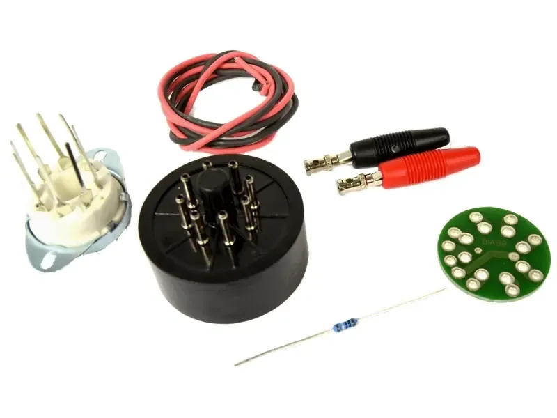
Tube Town B-Flex

XjFred

Member
Hello, everyone!

I’m planning to build a tube bass amp using this kit from Tube Town in Germany. It’s a kit inspired by Ampeg’s Portaflex series.

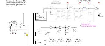
PSU schematic.jpg

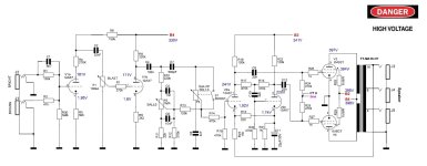
Schematic.jpg

I’m thinking of making a few modifications:
- Add a volume potentiometer (1 Mohm log) in place of resistors R14 and R15. Passinwind recommended a useful improvement: using a switchable potentiometer to add a bright cap, but I’m having trouble determining the value of that capacitor ( fc=1/2πRC).
- Use output jack with switching contact to incorporate a dummy load and prevent damage if the amp is plugged in without a load.
- Add a DI output before the volume knob
- Add a Stand-By switch on HV1/HV2.

I’d love to hear your thoughts. I’ve already built a pair of pedals based on kits designed by Nathan from Sushibox FX. Succesfully and I'm having lot of joy using them. But this will be my first DIY amp. I plan to connect it to an Ampeg SVT 210 cabinet.
 
Last edited:
The standby switch isn’t really useful. A MV definitely is. You could also play with changing the tonestack structure to give you more control and possibly make the bright cap on the MV less important.
 
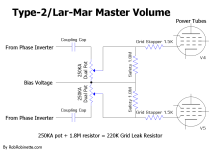
1. If I did a master volume, I’d use a post-phase inverter master volume. The Lar-Mar example works well.
2. The dummy resistor is going to be larger in size, so allow space!
3. DI out might work best off the R14/R15 going into the phase inverter.

4. I would see if there’s a way to bring down the plate voltages of B+1 and B+2. Sure, some 6v6gt can take up to 400vdc, but you’ll have to watch the bias. If you can get to 375vdc, they’ll be a bit happier
 
Quick look on schematic had me thinking it might be a noisy circuit and need tweaks f.ex. input resistor values.

Use output jack with switching contact to incorporate a dummy load and prevent damage if the amp is plugged in without a load.
Just solder 470-1000ohm 5W resistor across output jack leads and call it done.
but you’ll have to watch the bias
With that supply; definately!

Easy to do mods with turret boards. But why I haven’t looked TT kit prices before? Really affordable kits!
 
Thank you both. These are some things to think about before I place my order.

1. If I did a master volume, I’d use a post-phase inverter master volume. The Lar-Mar example works well.
I've found this schematic.

Type-2orLar-Mar_Master_Volume_Schematic.png

If I understand correctly, I'll need to replace R24 and R25 with a two-stage 250kohm log potentiometer. And add 2x1.8Mohm safety resistors to maintain the initial values of approx 270k (220k in that case).

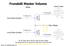
I also found a variation (Frondelli MV) :

Frondelli_Master_Volume_Schematic.png

Any thoughts about this one vs the Lar-Mar solution ?

2. The dummy resistor is going to be larger in size, so allow space!
You're right. I won't have enough space in the chassis to afford 3 power resistors for the outputs.

4. I would see if there’s a way to bring down the plate voltages of B+1 and B+2. Sure, some 6v6gt can take up to 400vdc, but you’ll have to watch the bias. If you can get to 375vdc, they’ll be a bit happier
OK, but won't that reduce the amp's power ? It's only 18W...

Quick look on schematic had me thinking it might be a noisy circuit and need tweaks f.ex. input resistor values.
Noise is definitely the last thing I want. What do you recommend regarding the input resistors ? Are you talking about R1 and R2 ?

Just solder 470-1000ohm 5W resistor across output jack leads and call it done.
OK, jacks with contact switch and 1Mohm resistors (only 5W ??) and this will allow me to use the DI out without any cab plugged in ?

As for adjusting the bias, I'm going to purchase this tool for precise calibration :

Again, thank you both. A lot of food for thougts here.
 
Last edited:
OK, jacks with contact switch and 1Mohm resistors (only 5W ??) and this will allow me to use the DI out without any cab plugged in ?
You misread good, for clarification and hazard safety note 470r-1000r aka 470 ohm to 1 kohm.

Bias probe is a gimmick if you don’t bias as your profession. Just stick individual 10r resistors between tube socket pin1+8 and GND. That’s your bias probe there to take accurate enough DMM reading for biasing. Just make sure you match resistors to each other close enough.

Noise is definitely the last thing I want. What do you recommend regarding the input resistors ? Are you talking about R1 and R2 ?
It really depends what you’re using the amp with. Maybe use stock values first and if needed adjust from there, 20-33K/470k-1M? But will it then have PortaFlex sound anymore, dunno!
 
Type2 Lar-Mar is the one that a lot of DIY people use. Make sure to have those safety resistors (2.2M is pretty common)

Dropping the voltage a bit does drop some output, but the difference between 5W (like a champ) and 18W when fully cranked is different but not insanely different (because volume and decibels are logarithmic).

I should stop before I get too deep over my head in knowledge. I know enough, but I haven’t built an amp in a few years.
 
Back
Top