Twill Deluxe - Great Barrier Keef

Build Rating
5.00 star(s)
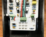
My second forray into pedal building, having completed a Dielectric Boost before. A similar circuit, and another satisfying build that turned out really well. Hardest part of this build is that the LED holes didn't line up with the PCB so I have to solder wires from the board to the LED legs. If there's an easy / more elegant way to do that well I'd love to know your thoughts for next time. I put some heatshrink over the connections just in case. Happy to say that the pedal fired up first time I plugged it in with no issues. It sounded and reacted exactly how I expected, even down to the boost not really doing much until you push it past the 3 'o'clock setting. That's a characteristic of this pedal. I actually have a Les Lius on hand to A/B it with and it's very close between them. It's a great pedal to get those driven tweed tones, from Keef Richards, Joe Bonamassa and Neil Young.
 

Attachments

  • Great Barrier Keef.jpg
    Great Barrier Keef.jpg
    465.1 KB · Views: 46
  • Great Barrier Keef Gutshot.jpg
    Great Barrier Keef Gutshot.jpg
    373.2 KB · Views: 50
Sorry to raise this post from the dead, but I just built one of these and ran into the same issue with the LEDs being too far from the board for the legs to reach.

Since you were looking for a more “elegant” solution (and if you haven’t yet found one). I made it a bit easier - especially if you ever need to pull the board in the future: I’ve taken to using 2-pin terminal blocks on the board. I did the same with the I/O grounds and power input.

In fact, so used a couple of 4 pin blocks for the stomp switches as well. I’m in the habit of building first and figuring out enclosure design later (or waiting for Tayda’s long lead time on powder coating > hole drilling > UV printing). In the meantime I’ll just 3D print an enclosure. I started using terminal blocks everywhere I would otherwise need to desolder/resolder to swap enclosures. Now I just like them and use them wherever I can as a convenience.
That is a brilliant idea. I'd thought about using something like that when I had two pickguards for a guitar and rather than having to get out the soldering iron it could be more easily swapped out. Have you found a particular style of terminal block that works well? I would worry about them knocking around in the pedal or the connections coming loose. But the prospect of being able to pull them out more easily or test them without having to install them fully is rather appealing.
 
That is a brilliant idea. I'd thought about using something like that when I had two pickguards for a guitar and rather than having to get out the soldering iron it could be more easily swapped out. Have you found a particular style of terminal block that works well? I would worry about them knocking around in the pedal or the connections coming loose. But the prospect of being able to pull them out more easily or test them without having to install them fully is rather appealing.
Take a look at how I used them on another build here:
https://forum.pedalpcb.com/threads/dr-robert-“pharmacist”-w-tayda-uv-print.27516/

They’re 2.54mm thread pitch PCB mount screw terminal blocks. I knew I didn’t want anything that “met in the middle” like spade connectors, etc. I initially thought of/tried little molex connectors, but these turned out to be vastly better. The pins are far more substantial than a lot of components, so I just bend and solder them and they stay perfectly secure. And unlike the molex ones, you solder one end (to your jacks, etc.) and you’re not stuck with the initial length of wire you chose. You just cut/strip the other end as necessary, insert and screw them down.

I just ordered a bunch more to stock up. This was the best “bang for the buck” deal I found (40 2-pin plus 20 3-pin for $7:

 
IMG_2305_polarr.jpeg Here’s my VERY hastily thrown together Aion Ares (ClinchFX EP-PRE) that I put in its temporary enclosure to test last night. Didn’t get to the terminal for the LED yet, but you can see where I used 2, 3 and 4 pin blocks. I’ll cut down the wires on either side and route the 4 in the middle beneath the board before it goes to its final resting place….
 
I'll definitely look into grabbing some of these and using them on some future builds and some troublesome past ones. I have had zero luck with anything from Aion FX, they just never want to work for me. I don't know if it's the way they have to be grounded and I'm doing it wrong, but it's just far easier on the PedalPCB designs. I need to put together an audio probe for troubleshooting purposes.
 
I’ve had equal success with Aion FX and PedalPCB, though I have to say I appreciate the greater detail/specificity in the Aion FX build docs.

The one major difference for me (and this is based on a small sample), is that when I’ve had to do a fair amount of desoldering, the Aion FX board was completely unscathed but the PedalPCB board was really roughed up (even losing pads and pulling up traces). I’m no hack at desoldering, and used the same methods on both (Engineer SS-03 and braid where appropriate).
 
Back
Top