Two LED's one switch

falco_femoralis

Well-known member
I'm trying to do a thing with a pedal that has a spdt on/off/on switch. I'd like to use a dpdt instead and use the second set of contacts to illuminate two LED's depending on switch position. So pos 1, green LED on, pos 3, blue LED on. But here's the kicker - pos 2, both on.

Is there a clever way of wiring this to make that happen? The first thing that came to mind is having both LEDs on by default, and a ground wire to the center pin of the switch which the switch then directs via pins 1 and 3 to the anode of either LED, shorting it out. But I imagine a dead short (with a 4.7k resistor) wouldn't be ideal?

Any suggestions?
 
You should be fine shorting an LED, I would just make sure to grab power and ground from the least interactive spots. You could even do this with a common cathode bicolor LED, you just need to scale your resistors so one color doesn't wash the other out in middle position.
 
You should be fine shorting an LED, I would just make sure to grab power and ground from the least interactive spots. You could even do this with a common cathode bicolor LED, you just need to scale your resistors so one color doesn't wash the other out in middle position.
What do you mean by "least interactive?"
 
In my mind, this would be a lot easier with an on on on switch.
Or a 3 pole switch.
Are either of those a viable option?
An On/On/On DPDT is not viable since Type 1 and Type 2 switches leave a set of contacts connected in center position. I assume the build docs specify On/Off/On so center position isn't in parallel with positions 1 or 3.
 
An On/On/On DPDT is not viable since Type 1 and Type 2 switches leave a set of contacts connected in center position. I assume the build docs specify On/Off/On so center position isn't in parallel with positions 1 or 3.
No, it would absolutely work for the LEDs. Not sure about the other half in circuit. Depends on what it's doing if the circuit can be adjusted(diode or cap switching, maybe the circuit can be changed). But for the LEDs , you just disconnect ground to one LED in up/down.
Center, both on.
 
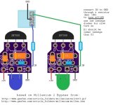
Would a double Millenium Bypass 2 be over-complicated? It turns off an LED when connected to ground through a high value resistor.
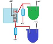
Otherwise you could just do the shorting out the LED method and use like 47k or higher resistors with high brightness LEDs.
 

Attachments

  • millx2_2.jpg
    millx2_2.jpg
    82.2 KB · Views: 10
  • shrtgnd.jpg
    shrtgnd.jpg
    14.3 KB · Views: 10
I wouldn't take power from anywhere close to opamps or transistors, the best points may be right off the power plug jack. I apologize if I wasn't clear, the point is to make sure the LEDs don't cause any audible changes when you flip the toggle switch.
Thanks, I gotcha. I'll grab the power from the LED circuit.

When the LED is grounded out (for example in pos 1 with one LED on, the other will have - applied to both pins) this would cause the power for the LED to go from + thru a 4.7k resistor then to -. Would that be an issue?
 
It shouldn't, I can test this circuit for you after work to make sure. I can also do up a diagram on DIYLC since I would need to do a visual confirmation.
 
Back
Top