TUTORIAL Two Sticks of Derm Fuzz

BuddytheReow

Breadboard Baker
Hey All,

Been a looooong time since I've posted one of these sweet breadboard tutorials. My new job is pretty demanding, so unfortunately I'm going to have to do this in parts. Please be patient with me. I should have this done in a day or two.

Two Stick of Derm Fuzz. As the name suggests, this is a great 1-knob doom machine. 9 resistors, 9 capacitors, 3 common transistors, and a volume pot. That's it. A bit more complicated than a Fuzz Face, but not by much.

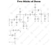
Below is the schematic and my finished breadboard. I will walk through how to transform one into the other shortly. Consider this post a sweet preview. Please keep scrolling through this thread for the rest of the steps.

BuddytheReow

1654713909984.png

1654713896585.png
 
Ok. First thing we need to do is set up the power section. Just a 47uf electro cap to ground to filter out the bad power. I find it easiest to save space on the board by simply sticking it in the power rails (long lead in the positive side).

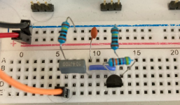
Once that's done, let's start with the actual circuit. Input to R1 and C1. R1 goes to ground (our pulldown resistor to stop any popping when engaging the stomp switch). C1 acts as a DC filter, and it should be noted that given its value (100n) it will allow most guitar signal to pass through. I threw the 1st transistor on the board just to see where I need to start placing any jumpers.

BTW if you put your output wire right after C1 and test it there won't be much change to the sound yet. So far, this is a good thing. You can try altering the caps values here, but wait until the finished circuit is done to start tweaking.

1654716815008.png
 
Let's start to set up Q1.

From the C1 we add C2 (220pf) to ground. THis is done to filter out some of the highs and reduce noise. We then jumper this intersection to the base of Q1. It is a common 2n3904. IMO you should always have these and 2n5088 laying around. Anyways, add R2 from the power rails to the collector of Q1 (the right pin in my pic). R3 then goes from the collector to base. The purpose of this resistor is to bring just a little bit of voltage to the base and turn on the transistor when engaged.

1654717206826.png
 
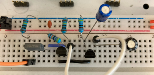
Let's work on Q2 now. From Q1 emitter (left pin) we add a jumper to Q2 base (middle pin). We also need to add a jumper wire from Q1 collector to Q2 collector to power up Q2. From the emitter of Q2 we need to add 2 components to ground: R4 and C3. The purpose of these 2 compoonents is to set the gain of this transistor set. From Q2's collector we need to add C4 which acts as a DC coupler. GIven the size of this cap it wont do any EQ filtering for guitar at least (haven't tried this on bass). What's actually happening in the circuit is that Q1 gets amplified and fed into Q2 for more amplification.

1654717637330.png
 
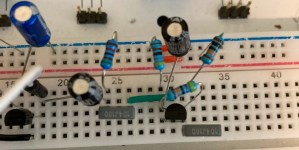
From C4 we need to add some more filtering and then hook up Q3. Adding R5 to ground right after C4 acts as a high pass filter and removes the super low noise (my calculator says 0.3Hz) that may get generated from the transistor set. We then add C5 (100n) as another DC coupler. This then gets jumpered to Q3 base.

For Q3, we will combine what was done on Q1 and Q2 in terms of connections: 100k resistor (R6) to collector, 470k resistor (R7) from collector to base, and a combo of 4.7k resistor (R8) and 10uf cap (C6) to ground. To finish it off, we add another 100n cap from the collector to the next stage. If you really wanted to, the way Q3 is connected in conjunction with C5 and C7 will act as a standalone circuit block and produce tone. I haven't tried it personally, but I know it will work based on my limited circuit knowledge.

1654718152068.png
 
Ok, we're almost done! Now we need to add a volume pot and the last bit of Eq filtering. I didn't feel like putting an actual pot on here so I just took a trimmer. They both perform the same function, but one is controlled with your fingers and the other is controlled with a screwdriver (or fingernails if you are not a nail biter, lol). Jumper C7 to pin 3 of your pot and pin1 to ground. Pin 2 will act as the output here. From the output you will need to add one more RC filter (resistor/capacitor) to finish this bad boy off. It looks kind of funky in the picture, but all we're doing is adding the output jumper and C8 together at the same junction. From the other side of C8 (100n) add R9 (51k). The result of this RC filter is a high pass filter allowing frequencies above 31Hz to pass through unscathed to the output wire.

1654718629484.png
 
Congrats! You now have a rockin doom machine at your disposal!!!

MODS
Some suggestions if modding is your thing (as a breadboarder I'm sure it is):

-First and foremost, try switching out the transistors for something else. You can try 2n5088, 2n222, 2n5089 for starters. Let your ears be the judge on this one. You don't even have to switch all of them out. Try swapping one at a time and see if that does the trick

-Try tweaking C1 to a lower value. It may not have the doom feel you're looking for, but it will change the tone

-While you're at it, try altering the other coupling caps as well and see if that satisfies you.

-R4/C3 and R8/C6 control the gain of each stage. You could try altering their values or even removing the caps for something different.

-C2 as noted above clips some of the highs off. You can alter this to your liking or simply remove it and see what happens.

-While such a simple circuit, it lacks tone control. Try a BMP, Marshall/Fender, or even a Baxandall stack here for some good tweakability. As I'm writing this I'm reminded to put a tutorial out there how to do a Marshall stack. It's now on my list. Sigh. The teaching/learning process never ends.


Happy Baking, y'all!!!!

BuddytheReow
 
Just added some 2n3904s to my cart!

This is a great excuse to get going on putting my protoboard together.
 
Where would you recommend adding a BMP-style tone control? I’d love to build one!
IMO, a tone stack would work best right after C7 and before the volume control. Keep in mind that a BMP tone control is passive and will drop the overall volume a noticeable amount. You can counter that by putting a recovery stage/booster right after it and before the volume pot. C8/R9, right after the volume control, is just an RC filter to get rid of super low frequencies (below 30Hz) so you should probably keep that in there.
 
Where would you recommend adding a BMP-style tone control? I’d love to build one!
I'd start with replacing R5 with a BMP-style tone control. C4 and R5 form a HPF at 0.312 Hz, I'd guess that wouldn't be missed too much if replaced by a full range tone stack. This way the existing emitter/follower stage at the end can act as a recovery stage. Maybe modify that stage for more gain, too.
 
Just built this circuit and oh man...I find it inspiring!
So I screwed up at first, got in a hurry and accidentally put a big old 220nF cap in place of the 220pF cap...lol.
I fired it up and was disappointed in the muffled sound lol. I thought, " this was not discussed in the brochure."
So I started reading and came across this thread. Then of course the "duh, you dumbass" moment occurred and I swapped it out for the correct 220pF.
Fuzz Awesomeness !!!
Then I put a treble boost in front of it. Pure insanity!!!
Now I wanna make one and pair it with a boost in one box!
Since you’ve got it on the breadboard, try wiring up a squidward right after it for additional awesome sauce 😎
 
Oh man great idea!
I am still examine this circuit and having a lot of fun. Let me ask you this, this circuit is very loud, plenty of headroom. Have you tried adding some clipping diodes into the circuit? Maybe something like red LEDs?
 
Oh man great idea!
I am still examine this circuit and having a lot of fun. Let me ask you this, this circuit is very loud, plenty of headroom. Have you tried adding some clipping diodes into the circuit? Maybe something like red LEDs?
I haven't personally done that, but sure. Give it a try. That's the beauty of breadboarding!
 
Back
Top