Unable to get jfet voltage low enough

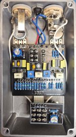
Hey, friends! I finally got around to building the Pineapple (Wampler Pinnacle). I found a thread giving the recommended values for biasing Q5 and Q6, but I need help getting the drain voltage below 6.19 and 7.09. I get sound in active and bypass, but the effect doesn't seem quite right. It's too fizzy and barky, if that makes sense (searching for adjectives to describe guitar tones is difficult). I'm assuming that it has to do with the jfet biasing. Suggestions welcome! Thanks in advance!
 
Last edited:
You didn't write anything about transistors.. did you use J201, what type (tht or smd). Are you sure Trim 1 and 2 are 50k and not a lower value. Are R14 and R22 1k and not a higher value.
Thanks! I needed to ask a more thorough question. I used J201 transistors pre-soldered on TO92 adapter boards. I had to mount them underneath the board since there wasn't enough room on top. I double-checked to make sure they were all facing the right direction. Trim pots 1 and 2 are both 50k (I double-checked). R14 and R22 are both 1k resistors.
 

Attachments

  • image000000.jpg
    image000000.jpg
    315.5 KB · Views: 15
  • Q-1201__11903.jpg
    Q-1201__11903.jpg
    138.9 KB · Views: 15
Question for ya: was this a kit, or did you independently source the components?

I ask because j201's can have quite a bit of variation between them. The boneyard sub-forum has a good article on this. Sometimes you gotta experiment with a few different components to get the circuit where it needs to be.

Personally, I'm a big fan of socketing basically any active component with more than two conductors. Those little SMD boards can be rotated 90⁰ too: that may help with getting those boards to fit up top.

Personally...I've invested a little coin in building up a little collection of jfets. It's too bad they're not being made in the TO-92 format anymore, but the SMDs certainly make storing hundreds of em easier.
I independently sourced the components. I believe the jfets came from Stompboxparts, who are usually reliable, but I totally get your point. I need to start socketing transistors since I already do so with ICs (and diodes sometimes). Thanks for the info, friend!
 
Can you measure Vp of the Q5 and Q6?
With 9V supply, J201 with Vp between -0.6V and -0.8V, 1k source resistor and 50k trimpot, you should be able to adjust drain voltage from VCC value down to about 1V.
You can try changing the trimmers to 100k. But, from my experience - here, you should be able to set the bias to 1/2VCC with drain resistance much lower than 50k..
 
I independently sourced the components. I believe the jfets came from Stompboxparts, who are usually reliable, but I totally get your point. I need to start socketing transistors since I already do so with ICs (and diodes sometimes). Thanks for the info, friend!
That's the rub... Reputable folks that put together kits tend to select Jfets that they know will work in the circuits.

Stompboxparts is indeed a legit place to get components: it's just that they're selling components that aren't specifically selected for the circuit you're building.

That's the rub: it's not about "good" or "bad" Jfets, it's about "correct for the circuit" or "incorrect for the circuit".

This was one of my early builds: there's stripboard layouts out on the interwebs that show ya how to build a tester for Vp and Idss. The cheap TC-1s on Amazon do an acceptable job too. I'd recommend either building one or buying the cheapie. Take notes, familiarize yourself with what works and what doesn't work on each circuit.

1000005949.jpg
 
Can you measure Vp of the Q5 and Q6?
With 9V supply, J201 with Vp between -0.6V and -0.8V, 1k source resistor and 50k trimpot, you should be able to adjust drain voltage from VCC value down to about 1V.
You can try changing the trimmers to 100k. But, from my experience - here, you should be able to set the bias to 1/2VCC with drain resistance much lower than 50k..
Thanks, friend! Excuse my ignorance. My minimum drain VCC is 6.19 (Q5) and 7.09 (Q6). (The maximum is 9.06 on both.) My problem, as stated at the top of the thread, is that I can't get them lower than that with 50k trimmers. But, that's just restating the original problem. How do I fix the issue?
 
I've build the BSIAB2 which is a very similar circuit, but used 2n5457s. If you have some to try, pop 'em in and see if they can be biased.
I should have socketed them! LOL! All the jfets I had available were SMDs mounted to TO92 adapter boards, so I used pin headers and soldered them to the PCB. Maybe I'll see if I can desolder Q5 and Q6 and sub in some 2N5457s. Thanks for the advice!
 
That's the rub... Reputable folks that put together kits tend to select Jfets that they know will work in the circuits.

Stompboxparts is indeed a legit place to get components: it's just that they're selling components that aren't specifically selected for the circuit you're building.

That's the rub: it's not about "good" or "bad" Jfets, it's about "correct for the circuit" or "incorrect for the circuit".

This was one of my early builds: there's stripboard layouts out on the interwebs that show ya how to build a tester for Vp and Idss. The cheap TC-1s on Amazon do an acceptable job too. I'd recommend either building one or buying the cheapie. Take notes, familiarize yourself with what works and what doesn't work on each circuit.

View attachment 81019
Thanks! That makes sense. I don't know if a discrepancy between jfets would cause such a drastic problem (Q5 minimum VCC of 6.19 and Q6 minimum VCC of 7.09), but maybe that's what is happening.
 
My minimum drain VCC is 6.19 (Q5) and 7.09 (Q6). (The maximum is 9.06 on both.) My problem, as stated at the top of the thread, is that I can't get them lower than that with 50k trimmers. But, that's just restating the original problem. How do I fix the issue?

VCC is more or less supply voltage. That would be around 9V (voltage of the power supply minus voltage drop on a protection diode).
Your 6.19V is drain voltage, not VCC. VCC is constant. Drain voltage changes with trimpot adjustment.
Vp - it's a parameter of the transistor. You have to remove jfet from the pcb and measure it off the circuit.

Here you'll find some info on how to measure Vp
 
Thanks! That makes sense. I don't know if a discrepancy between jfets would cause such a drastic problem (Q5 minimum VCC of 6.19 and Q6 minimum VCC of 7.09), but maybe that's what is happening.

I did a "desolate fuzz" as one of my early builds. That one required Vp and IDSS values that were right on the edge of their stated ranges.

It sounded reasonably...eh...fine ish. On my first attempt. But it didn't have any of that splattery awful brokenness that I had come to live from the demos.

Swapping those with some that I had tested, once I knew what I was looking for, cleared that right up.

The general gist: Jfets aren't super easy to make to super tight tolerances. Manufacturers sell with a wide range in order to keep yeilds up and folks that design around Jfets tend to use trimmers to bias...or relegate them to tasks that are easier to control.

Trimmers can only do so much though, and sometimes they can't be adjusted enough to reach the desired result.
 
VCC is more or less supply voltage. That would be around 9V (voltage of the power supply minus voltage drop on a protection diode).
Your 6.19V is drain voltage, not VCC. VCC is constant. Drain voltage changes with trimpot adjustment.
Vp - it's a parameter of the transistor. You have to remove jfet from the pcb and measure it off the circuit.

Here you'll find some info on how to measure Vp
Cool! Thanks!
 
Back
Top