Vero Designer - Generate vero from any schematic!

blazethablunt

New member
Hey everyone, first post here.

I’ve recently released a web application called Vero Designer and thought this would be a good place to share it.

The basic workflow is pretty simple:

Draw the schematic → Generate Vero → Edit the layout

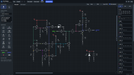
The schematic editor lets you place and wire the components. When a component is selected, you can rotate, flip and duplicate it from the left sidebar. Copy and paste are also available through the regular Ctrl/Cmd+C and Ctrl/Cmd+V shortcuts. For more useful shortcuts, visit the help section.

Available components:

• Resistors
• Capacitors
• Op-Amps
• Transistors
• Tubes
• Diodes
• Potentiometers
• Switches
• LEDs
• Trimmers
• 5v voltage regulator
• Other ICs


Some other useful features:

• Update IDs – Reassigns IDs to all schematic components (schematic page only)
• Update Vero – Applies schematic changes to the existing vero layout without generating a new layout
• Regenerate layout – Generates a completely new layout after major schematic changes
• Auto describe – Generates a description for the layout based on the components used
• Standing resistors – Optional feature to save space, off by default

You can save projects and open them later, give the circuit a name and edit the description. You can also import KiCad files.
Both "Schematic" and "Vero" pages have buttons for undo/redo changes, and export a PNG image. export BOM is available on the vero page.

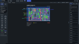
Once the schematic is ready, Vero Designer automatically generates a vero layout. The generated board isn’t locked either. Components, links and cuts can all be edited afterwards.

You can also download the app and use it offline.

For more details, please visit the github page. You will also find a folder with layouts made by me and other users, including some that were built and verified.
Let me know what you think.

Web app: https://verodesigner.vercel.app/

Github: https://github.com/blazethablunt/VeroDesigner

Youtube walkthrough:

vero designer 1.3_ve.png vero designer 1.3_sc.png
 
Hey, I think I saw this on HN! Nice work, I tried it out on a few simple circuits, but haven't verified them yet.
 
I like the idea of an automatic Vero layout thing. I have always enjoyed coming up with my own layouts to suit my idiosyncratic requirements but sometimes more complex circuits defeat me. So I wonder if I would use this as more of a starting point than producing a finished article? It's an interesting idea, and one I suspect would be tricky to design!
 
I like the idea of an automatic Vero layout thing. I have always enjoyed coming up with my own layouts to suit my idiosyncratic requirements but sometimes more complex circuits defeat me. So I wonder if I would use this as more of a starting point than producing a finished article? It's an interesting idea, and one I suspect would be tricky to design!
Thank you!

For smaller circuits, the app usually generates a very efficient layout. For the more complex, bigger circuits it might not always generate the most efficient layout as far as size, so you’re supposed to look at the generated borad as a starting point. You can edit the board, and re-organize every component, cut, link, change the size of the board and move edge connections.

I used to design these manually as well, and I wanted to save some of the time I was spending on it which is why I created the app. I hope you will find it useful
 
This is great! I've been making use of it recently, so far largely to create schematics for circuits for which I have only a component list and netlist (due to my use of low-end LLMs - but that's a different story!) Vero Designer has been extremely useful for this; thank you!

Not sure how interested you may be in suggestions/feedback - you probably have plenty on your plate already - but here's a couple of points that occurred to me as I was using it. Apologies if any of these are accounted for by existing features that I've just failed to find!

1) It would be great if there was a button to temporarily lock the component connections as you're dragging them (or wires) around the screen. I found it's otherwise quite easy to accidentally make changes to the circuit, sometimes without noticing.

2) Where two wires that are part of the same net overlap and travel the same path for some distance, and then part company and head off in different directions, it would be great if a blob could appear at the junction to indicate that these are part of the same net. It can otherwise not be immediately obvious whether there is a net junction at this point, or entirely separate wires that just happen to cross or share part of the same route. Of course the colours do help with this to some extent.

3) I was caught out by the fact that the contact pin numbering scheme for the DPDT switch is non-standard: Vero Designer uses 1 and 4 as the common contacts for each half of the switch, whereas I think using 2 and 5 would be more conventional. This caused some confusion when discussing my circuit with the LLM, until I worked out what was going on!

4) Obviously it would be ideal to have a wider selection of components available - I imagine this may happen as time goes on. (I do thank you for the inclusion of the 2164 quad VCA, as this happens to coincide with one of my current projects!) It would be good though if there were more "generic component" stand-ins for when a specific component isn't included. I know there's a generic 8-pin IC, and I did at one stage manage to create a generic 16-pin through some slightly accidental process. I guess this is still work in progress.

I haven't played too much with the board layout features so far. I'm most interested in using it to create perfboard layouts, which I know is a recent addition - thank you again. I realise the perfboard feature is still in beta, so I'm excited to see how that comes along.

I hope this comes over as constructive feedback and not criticism - that's certainly how it's intended. Thank you for your work on this excellent project!
 
This is great! I've been making use of it recently, so far largely to create schematics for circuits for which I have only a component list and netlist (due to my use of low-end LLMs - but that's a different story!) Vero Designer has been extremely useful for this; thank you!

Not sure how interested you may be in suggestions/feedback - you probably have plenty on your plate already - but here's a couple of points that occurred to me as I was using it. Apologies if any of these are accounted for by existing features that I've just failed to find!

1) It would be great if there was a button to temporarily lock the component connections as you're dragging them (or wires) around the screen. I found it's otherwise quite easy to accidentally make changes to the circuit, sometimes without noticing.

2) Where two wires that are part of the same net overlap and travel the same path for some distance, and then part company and head off in different directions, it would be great if a blob could appear at the junction to indicate that these are part of the same net. It can otherwise not be immediately obvious whether there is a net junction at this point, or entirely separate wires that just happen to cross or share part of the same route. Of course the colours do help with this to some extent.

3) I was caught out by the fact that the contact pin numbering scheme for the DPDT switch is non-standard: Vero Designer uses 1 and 4 as the common contacts for each half of the switch, whereas I think using 2 and 5 would be more conventional. This caused some confusion when discussing my circuit with the LLM, until I worked out what was going on!

4) Obviously it would be ideal to have a wider selection of components available - I imagine this may happen as time goes on. (I do thank you for the inclusion of the 2164 quad VCA, as this happens to coincide with one of my current projects!) It would be good though if there were more "generic component" stand-ins for when a specific component isn't included. I know there's a generic 8-pin IC, and I did at one stage manage to create a generic 16-pin through some slightly accidental process. I guess this is still work in progress.

I haven't played too much with the board layout features so far. I'm most interested in using it to create perfboard layouts, which I know is a recent addition - thank you again. I realise the perfboard feature is still in beta, so I'm excited to see how that comes along.

I hope this comes over as constructive feedback and not criticism - that's certainly how it's intended. Thank you for your work on this excellent project!
Thank you for the kind words! Im glad you found it useful.

All feedback is welcome but not all suggestions/requests are implemented. a temporary lock for example is a nice idea and maybe i will add one but i have more important features on the list so things like that will come later.

I won't be adding a blob on wires because wires of the same net share the same color. I don't know how that is not immediately obvious. I know it makes for a different looking schematic when you compare to most "traditionally" drawn schematics but im fine with it. I feel like the nets having the same color is more than enough to distinguish which net the wire belongs to and i also never heard that from any other user. The blob is added because all the wires are usually black.

DPDT and other switches will be fixed, i did not realize that there's an issue with them, thank you for pointing that out. I dont use a lot of switches so that probably why i missed it. The component list is always updated but the goal of the app is not to have every component in existence, rather just the most used ones for both pedal and synth circuits. If a certain transistor you want is missing in the app for example, you can just take any other transistor, rename it, and change its pinout using the new pinout editor. same thing for DIP ICs, the generic IC feature you mentioned can handle 4, 6, 8, 14, 16, 18 and 20 total pins. You can change its size by dragging the bottom notch up or down. I will also add a "footprint creator" for users who want a whole costum componet to do whatever with it, but that will also come later.

The perf router is a new feature and will be improved but its already working well, You can see some of the layouts i created with it in the github repo.

Thanks again!
 
Ah, I had missed the fact that the generic IC is resizable by dragging - thanks for that tip!
It would be good if you could rename a generic IC in a similar way to how you can with a transistor - I'm guessing that might be on your list already, unless I've also missed the existing method for doing this...

I think the reason I found myself wanting blobs on net junctions was that I was working with a number of ICs with lots of pins, so there were a lot of crossing wires and I was running out of enough colours to keep everything clearly distinguishable. I think I was also thinking that there might be circumstances where I wanted to print out a schematic, and I don't have a colour printer. I can see how neither of these observations would feature significantly on your to-do list! If I want an all-black version to print, I can add my own blobs! 😁
 
Back
Top