Waddle Box Issue

DPM309

New member
Just completed a Waddle Box build using the PedalBCP board. Got it working right away but am having issues with the controls. If I turn up the sensitivity control up, the signal gets really muddy/bassey. This happens from about 9 o'clock up to all the way and doesn't matter where the Range control is set. Took it apart and double and triple checked all connections, component values, etc. I am getting the right sound on this but the sensitivity control does not seem right.
Here are my voltages on the ICs:

IC1 P1 4.63, P2 4.62, P3 4.53, P4 0, P5 4.53, P6 4.63, P7 4.66, P8 9.3

IC2 P1 1.1, P2 4.62, P3 4.64, P4 4.64, P5 5.71, P6 0, P7 5.70, P8, 4.65, P9 4.62, P10 5.62, P11 9.3, P12 5.67, P13 4.63, P14 4.64, P15 1.1, P16 1.1

Any ideas?
 
Post a pic of the board.
Did you substitute any of the parts?
The IC voltages look good, the voltages on IC2 pins 2 & 15 look slightly suspicious, but are probably ok. I wouldn't expect pins 15 & 16 to be at the same voltage, but I don't think that's related to the problem.
 
I made this pedal for my bass player and he likes the sound he gets from it even though something doesn't seem right. Did not get a chance to take picture before I turned it over to him but I will try to get it back from him to get some pictures. I have built over 50 pedals, including the Mag Delay from PCB and this is the first time this has come up.
 
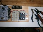
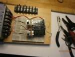
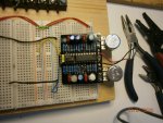
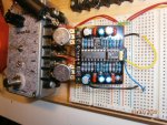
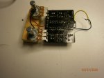
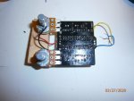
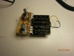
Decided to build another one of these while I am stuck at home like everyone else. Same issues as with the first build. Double and tripled checked all components etc. Here are a couple of pictures of my build. Have not boxed this one yet but hooked it up to my breadboard to check it out. Am getting great sounds out of this on both bass and 6 string but still having the issue with the sensitivity control. Re checked the voltages and they are about the same as my previous voltages with the exception of IC2, pin 2 which reads 1.3VDC. Hope these pictures are clear enough.
 

Attachments

  • P3270185.JPG
    P3270185.JPG
    112.9 KB · Views: 15
  • P3270188.JPG
    P3270188.JPG
    115.5 KB · Views: 16
  • P3270189.JPG
    P3270189.JPG
    111.5 KB · Views: 16
Sorry about that. Try these out. Am having trouble getting a good picture of the backside of the board. Checked R7 and the solder joint looked good. Also cleaned up a couple of tiny solder blogs off the underside but that did not change any of the voltages.
 

Attachments

  • P3270190.JPG
    P3270190.JPG
    151.6 KB · Views: 14
  • P3270196.JPG
    P3270196.JPG
    90.7 KB · Views: 15
  • P3270197.JPG
    P3270197.JPG
    89.6 KB · Views: 10
  • P3270199.JPG
    P3270199.JPG
    72.2 KB · Views: 9
That's not right. Should be about 4.5V. Check R101 and R102. Wrong value, bad solder joint or short. There are other places where VREF could be shorted to +9V, but start there. Do a thorough visual inspection of the solder side of the board, using magnification. Your pix of the backside are useless for that.

BTW, I meant to ask you to measure IC2-3, but we're past all that now. The problem is with VREF.
 
Could not get rid of the glare when trying to get a picture of the underside. The ground wire was pulled out of my breadboard. R6 and R7 now 4.65Vdc. IC1-3 now reads 4.4Vdc.
 
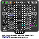
R10 is 22K, but from a different manufacturer (had 1 left in by stash before I ordered additional ones). Am getting continuity between all of the points you marked. Like I mentioned previously, I am getting good sounds out of this with the sensitivity all the way down. Increasing the sensitivity above 3 (9 o'clock) seems to strip off all of the highs. Does not act like the demo video of the DOD FX25. Both the Waddle Box and DOD FX25 schematics look the same except for different numbering on the ICs. This is the 2nd one of these I built with the same issues. Has anyone else run into this?
Thanks
If it was me, I would try a A100K Pot so you have a wider sweep, Can't hurt to Try.
If you have not removed a Pot before, I would sacrifice the Pot & cut the Outer 2 legs so you can heat and remove centre leg (Lug 2).
then just heat & lift out outer legs separately.

If you have experience with Solder Sucker & Wick, Use them to remove Solder from Pot Lugs.

Members, feel free to comment if you have built this Fussy pedal.
 
According to the schematic, the SENSITIVITY pot is wired backwards. Turning it CW reduces sensitivity. At 9:00, you have the sensitivity nearly maxed out. An A-taper pot might help. Won't change the SENSITIVITY range, but will make it easier to dial-in at the CCW end. I wonder why C2 is only 1nF. Cuts off the freq response of the envelope detector below 1KHz. Every sch I've found on the 'net has it as 1nF. I'd see if making C3 bigger helps. Try tack-soldering a 10nF in parallel with C2.
 
Back
Top