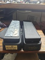
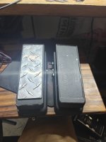
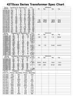
Wah Inductors. No hype. Just measurements.

Yeahhhh. Fuckin, I can't make heads or tails of it.

The difference is *extremely* minute. Tested driving both a 1meg load and a 5k load. The load makes a big difference, but this partial AC bypass barely registers on the graph.

Huh. I'm flummoxed.
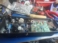
 
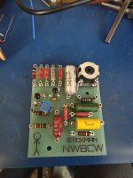
Doing a little bit of an experimental build here. Mostly stock, except for the added adjustable gain on Q1 and the range cap.

Its not as clean as I want it to be, just a prototype.

The range switch on the wah is gonna start from a 8.2nF baseline and. Five positions for parallel caps: empty, 1.8nF, 4.7nf, 6.8nf, and a 13nf.

Definitely need to design a switch-mounted daughterboard for this setup, though.

Also added a10pf cap across the collector and base of each transistor. Miller capacitors. Good for noise rejection and trimming the highs a touch.

Just slapped it together. We'll see how she behaves tomorrow.


1000059146.jpg
 
Doing a little bit of an experimental build here. Mostly stock, except for the added adjustable gain on Q1 and the range cap.

Its not as clean as I want it to be, just a prototype.

The range switch on the wah is gonna start from a 8.2nF baseline and. Five positions for parallel caps: empty, 1.8nF, 4.7nf, 6.8nf, and a 13nf.

Definitely need to design a switch-mounted daughterboard for this setup, though.

Also added a10pf cap across the collector and base of each transistor. Miller capacitors. Good for noise rejection and trimming the highs a touch.

Just slapped it together. We'll see how she behaves tomorrow.


View attachment 123556
What's that little board between the main pcb and the rocker?
 
My little mosfet reverse/over voltage protection and power filtration board.

Got a dip switch in there to remove the series resistor should someone have a good quality PSU to power the thing with. So, ya know, your 100 ohm resistor isn't artificially lowering the voltage the circuit sees. By an infinitesimally small amount.

Yeah. Its way overkill.
 
1000059151.jpg

Another!

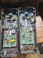
I'm redesigning the turret board to make it slightly smaller and to move the inductor away from the right hand side. Tends to crowd the 9v Inlet a touch.

So, this is my last of my V1 boards that I made. This guy gets a 47k input resistor, adjustable Q1 gain, an input cap I pulled from an old organ board, 2N3565s, a mix of metal film and carbon composition caps, Miller caps, and the range cap is NOS Russian PTFE.

Why? Because I felt like it.
 
Almost forgot:

This is a tweak I picked up from the EVH wah. It replaces the 220nf cap that connects to the "output" pin on the potentiometer.

Aint gonna make a load of difference. But it's there.
 
It's something to try on downtuned bass, I did notice something happening when I did it to my EB wah and a ShamWah board, but it's subtle.
 
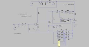
Jam Wahcko schematic.jpg

And the Wahcko trace.

Differences with the standard wah circuit:

- Most obvious off the bat is the 6 way selector switch. Same way Dunlop used to do it.
- Variable Q1 gain. Metal film 100 ohm resistor from Q1 emitter into a 500 ohm trimmer, to ground.
-Split the PSU capacitor into two: one before the 100 ohm resistive element of the RC LPF, the second after.
- BC109C transistors (CDIL)
- 2.2Meg pull down resistors on the input and output
- "proprietary buffer-less fuzz worker wither" is just a 10K ohm series resistor, a 470pF cap to ground to tame the highs, and a completely baffling 470nF capacitor in series with the lot.

Everything in the standard Wah Schematic + the series output resistor are carbon composition, with the exception of the Q1 emitter noted. The trimmer they use has a carbon resistive element. (Piher trimmer)

All 2.2Meg resistors are metal film. The PSU low pass filter resistor is also metal film. All film caps appear to be polyester.

Potentiometer...well now. Honestly: this looks like one of the cheap logarithmic potentiometers you can get anywhere. Doesn't prove that is the case, but certainly raises an eyebrow.
 
Back
Top