CONTEST What? Another Contest?

CONTEST
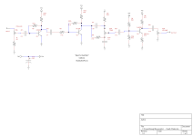
Those are odd-ball values. Where do you get 4.4M resistors and why not use a 4.3M or 4.7M?

Don't get me started on traces found on gear forums.
 
  • Like
Reactions: fig
I made headway on my project! I installed Diptrace. You mean I can't just take a picture of the breadboard and import it into this and see a schematic? Ain't that a hole in the boat?

Has anyone thought to request this feature? Oh well, they probably wouldn't have it ready by the contest deadline, do you think?
 
I can get you as close as 4.42M but it's SMD. (not the point though)

What I was getting at is there is no need to hit an exact resistance value there. When I see a schematic with a screwy value on it, it makes me wonder if it's a typo and if so, are there any other typos.

I made headway on my project! I installed Diptrace. You mean I can't just take a picture of the breadboard and import it into this and see a schematic? Ain't that a hole in the boat?

I think you have to actually run DIPtrace before a schematic comes out. ;)
 
If it works, it works. Entries that do not work are disqualified based on Rule #3. Sometimes it's not black & white...

When I hired in at an undisclosed aerospace company back in the '80s, they guy I replaced had quit because he was tired of working for a physicist who designed circuits that didn't work. The story I was told was that Dr. Science had designed a circuit that when it was first powered on, it blew a few parts and then started functioning. My predecessor was instructed to build another one and he could not or would not do it.
 
Here's another one I cooked up today. This one uses 3 different transistors and a tweaked BMP tone stack. It has some of the octave harmonics come through, but not as much as my previous entry. This one is more low-end oriented and really shines with downtuned guitars or perhaps even bass, although I don't have a bass currently to try it out on. You hear a little bit of gating since the signal is hitting the power rails so hard and less so if you have single coil pickups. With that in mind I decided to put in the PREGAIN control. A lot of the gating goes away if you run this at 18v. I consider this a growly doom machine but better tweaked that before.

I was having trouble naming this one and thought about all the quirky things with my cat (the main source of my entry names as well as my avatar). Buddy likes to sit on the dinner table with us while we eat and pokes his head occasionally into our plates and drinks to sniff around although we discourage that. We noticed very early on that he doesn't like seltzer water; I'm assuming he doesn't like it because it tickles his nose a bit too much. He runs away when we unscrew the tops of the bottles since he knows what's inside. Anyways, I call this one DEATH WATER. Breadboard pic to follow.
 

Attachments

  • Death Water.png
    Death Water.png
    14.3 KB · Views: 17
  • Like
Reactions: fig
And the breadboard pic. I have a 1m pulldown resistor toward the beginning of the circuit that was omitted from the schematic, but it is good practice to keep it in. I also took out the 100u power filter unknowingly before taking the pic.
1643154924357.png
 
Ah, I missed your point. I started with a 2M2, then I doubled it for 4M4, and finally replaced the mess with a 4M7.

I think I figured out how to make the Sustain pot = Blend. I’ll fix the notation when I update the schematic.
Did you build this? I just finished running sims and saw some interesting stuff. Onto the breadboard it goes.
 
If it works, it works. Entries that do not work are disqualified based on Rule #3. Sometimes it's not black & white...

When I hired in at an undisclosed aerospace company back in the '80s, they guy I replaced had quit because he was tired of working for a physicist who designed circuits that didn't work. The story I was told was that Dr. Science had designed a circuit that when it was first powered on, it blew a few parts and then started functioning. My predecessor was instructed to build another one and he could not or would not do it.
Fackin rocket scientists. Sheesh.

9b764a74-0396-4c07-a3d5-4724c330db33_text.gif
 
  • Haha
Reactions: fig
I was just running sims on the Plops of Doom prior to breadboarding it and now this!
I just finished posting an “experiment” I did in my “Buddy’s Breadboard” thread. I dialed in a sound I liked and started building from there. While all the circuits I’ve submitted aren’t finely tuned they do have different sounds. At this point it’s quantity over quality (what do I have, 5 now?). Either way I’m enjoying this mad scientist phase of mine. I really should get back to soldering soon before my breadboard gets too loafy 😂
 
Originally, I did not have the blend pot. But I think it is a good addition. When I ran it into a big muff, I thought it sounded best with a small amount of plain signal. But a small change of either blend or sweep could quickly go from “cool sound, bro” to “that’s gross”. And the same sweet spot doesn’t work the same for a clean amp vs dirty amp vs dirt pedal.

This has sent me down a rabbit hole reading about wahs and filters.

Edit: I also tried a larger range on SWEEP. Above 75k, my ears couldn’t hear any change. And it seemed like the best tones were around 5k and less useful above 10k. So I switched the pot to give better control at the low end. But I wonder how much of that is dependent on the rest of the equipment.
 
Last edited:
Filters don't just vary the gain as a function of frequency, they also vary the phase. The BLEND pot is mixing signals that are in phase at some frequencies and out of phase at other frequencies. When the BLEND pot is at one extreme or the other, the frequency response is pretty straightforward. It gets complicated when BLEND is in the middle. The BLEND pot definitely adds another dimension to the filtering. With the right BLEND setting, you can dial-in a pretty deep notch. I agree, it's a good addition. If you like mixing in just a little dry signal, then an A-taper BLEND pot may be more to your liking.
 
Back
Top