Have a few boards coming - what GREEN LEDs to go with the GL5516 LDR?
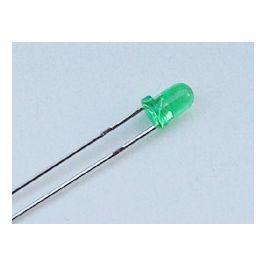
Standard ?
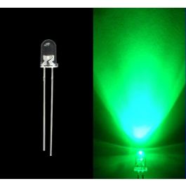
Super Bright?
Standard ?

Super Bright?

