What jacks to use for dual effects loop switch?

Elktronics

Active member
I’m having trouble finding suitable jacks for the dual effects loop switch, and for the power I/O module. Would anyone happen to have a link? I can find similar jacks that match the foot print, but not with the right washers.
Thanks,
 
That's the ones. I'll try to have some documentation posted shortly, but just in case....

Assembly is much easier if you go in this order:

1) Mount the 3PDT footswitches and LEDs in the enclosure first
2) Install resistors on PCB
3) Install DC jack on PCB
4) Install 1/4" jacks on PCB but do not solder yet
5) Connect battery snap to PCB
6) Insert PCB into enclosure and fit onto footswitches, adjust footswitch height as needed
7) Tighten nuts on 1/4" jacks, making sure the DC jack is aligned properly
8) Solder 1/4" jacks / 3PDT / LED

If you install the 3PDT footswitches onto the PCB before mounting it in the enclosure you won't likely be able to maneuver it into place.

Soldering the 1/4" jacks after tightening the hardware allows them to adjust to the slope of the enclosure wall without putting stress on the solder joints.


Here's the parts list:

1 x 125B enclosure (obviously)
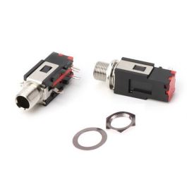
6 x 1/4" Jacks

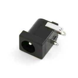
1 x 2.1mm PCB mount DC jack

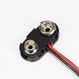
1 x 9V Battery Snap (this one is much nicer than the other two Tayda carries)

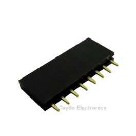
1 x 8-pin Female Pin Header

2 x 4.7K resistors

2 x LEDs (Loop indicators, your choice)

2 x LED bezels/lenses (if desired)

2 x 3PDT footswitches
 
Last edited by a moderator:
Silly question, but what is the 8-pin female header for?

1620829051958.png

It goes right here. The purpose is to prevent the battery from falling inside the enclosure since the PCB sits a little higher than normal.

The board was originally going to use another method but that part has become hard (impossible) to find, so you'll need to clip four pins from the header and it'll drop right in.

Of course you don't need it if you don't plan to use a battery.


I'll post a pic of my build shortly.
 
View attachment 11756

It goes right here. The purpose is to prevent the battery from falling inside the enclosure since the PCB sits a little higher than normal.

The board was originally going to use another method but that part has become hard (impossible) to find, so you'll need to clip four pins from the header and it'll drop right in.

Of course you don't need it if you don't plan to use a battery.


I'll post a pic of my build shortly.

Amazing, thank you so much! Yes, I would love to see a pic, as this is EXACTLY what I have been looking for, and wished I had access to for years. Pairing this with my Hotone Patch Kommander would give me access to exactly what I have desired for looping in effects. You guys are AMAZING! Only problem now is finding a way to make more money to build and play it all.. lol
 
That's the ones. I'll try to have some documentation posted shortly, but just in case....

Assembly is much easier if you go in this order:

1) Mount the 3PDT footswitches and LEDs in the enclosure first
2) Install resistors on PCB
3) Install DC jack on PCB
4) Install 1/4" jacks on PCB but do not solder yet
5) Connect battery snap to PCB
6) Insert PCB into enclosure and fit onto footswitches, adjust footswitch height as needed
7) Tighten nuts on 1/4" jacks, making sure the DC jack is aligned properly
8) Solder 1/4" jacks / 3PDT / LED

If you install the 3PDT footswitches onto the PCB before mounting it in the enclosure you won't likely be able to maneuver it into place.

Soldering the 1/4" jacks after tightening the hardware allows them to adjust to the slope of the enclosure wall without putting stress on the solder joints.
Could you please put this information on the "Additional Information" section of the PCB. Because I'm pretty sure that someone might not have done it in that order and butchered an enclosure.
 
Any quality issues with using those jacks from Tayda? I prefer to spend a bit more on jacks for long term reliability, but I really want to use the power i/o module for all future builds.
 
The jacks are ok, be careful with the power jack though. On Mine the center pin has started to loosen. There’s no way to get this out to fix it if the jack goes without desoldering the switch
 
Could you please put this information on the "Additional Information" section of the PCB. Because I'm pretty sure that someone might not have done it in that order and butchered an enclosure.
Funny part is, I actually READ this information, and still screwed up.. needless to say, this PCB exits in a 1590XX enclosure, Why? Because bigger DOES matter, not because I messed up or anything........ lol
 
Hi all, new here. i know this is a goofy question, but when you have both loops off do you still get the main dry signal through? then will loop 1 feed in to loop 2? i'm wanting to keep drives on one loop and modulation on one loop and be able to mix and separate.
 
If nothing is plugged into the loop jacks, no sound will come out at all when you turn the switches on. But the sound comes through normally when the switches are off, assuming the signal can pass through the pedals in the loop
 
Back
Top