What to make with 30-50 hFE Germaniums

This has been my main pedal since build.

1753252968554.jpeg
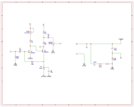
Q1-2 use germ-transistors you have, 30-60hfe.
Q3 germistor or Si. I used really high gain darlington, but find no use for MORE-switch (boost) as darlington transistor used takes off fuzz’ edge too much.
 
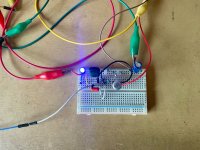
time to get a breadboard.

im serious, if you really want to get a quick tangible grasp on what to expect from your devices, pick a circuit, breadboard it, and see how you go.
then when you find something doesn't sound (or measure) right or whatever, it's as easy pulling a resistor and plonking a different value in there and hearing the difference immediately.
people can talk numbers and theory all day, but none of it really means shit until you hear things for yourself.


perfect candidate for your first breadboard project

Ok, so I have decided to try my hand at the PNP Ge LPB-1 breadboarding. And wouldn't you know it, there's already a guide to do that (sort of)

I wanted to ask a clarifying question though, in this example below, this to me looks a lot like the "turning the circuit upside down" mentioned in the Small Bear article on the Rangemaster.

Specifically:
I have a PNP device, and I really want to build and run negative ground. Can I "turn the circuit upside down" to do that?

A: It has been done, it sometimes works and sometimes oscillates badly. Not recommended.

However Barbarach has this to say:
This is important because lots of times it is said that circuit can be adapted from NPN to PNP transistor by simply reversing battery polarity. In reality, it is slightly more complicated than this.

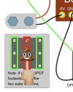
You only swap polarity for the amplifier – and that’s what I highlighted above. If you’d swap the polarity completely, jacks would be connected to 9V instead to GND and that might not be the healthiest option for subsequent pedals/amp.

I feel like I'm missing some understanding here, whether it be what "swap the polarity completely" actually means or otherwise. Why would simply swapping the battery polarity affect the jacks?

1753315285451.png
 
Why would simply swapping the battery polarity affect the jacks?
the jack sleeve also goes to ground.
if there is +9V going to ground, and therefore also the jack sleeve, this can affect other pedals in the signal chain, as all of their jack sleeves will have continuity to the same ground (via patch cables).

this is explained well here:

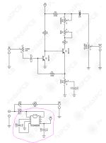
you might notice many pedalpcb boards that utilize PNP transistors in 'positive ground' vintage circuits are often equipped with a chargepump circuit to invert the power supply from +9V DC to -9V DC - this allows the ground to remain 0V DC/'neutral', and therefore not interfere with other pedals that might be in the signal chain.

e.g.
1753319628412.png
here, the segment circled in pink inverts the power supply from +9V to -9V.


for your breadboard experimentation (where you're not going to be hooking up other pedals), you can simply hook up the +9V supply to ground, as per the first example in the link above:
1753319995710.png

also, read this:
 
How did vintage Fuzz Faces and Rangemasters handle this problem then? Given they would be connected to an amplifier down range?

Once I built something permanent I will definitely use the charge pump inverter.
 
the jack sleeve also goes to ground.
if there is +9V going to ground, and therefore also the jack sleeve, this can affect other pedals in the signal chain, as all of their jack sleeves will have continuity to the same ground (via patch cables).
This is not necessarily true. You can use 0v as ground for the jack sleeve, rather than 9v, in the scenario that you outlined and it will work fine.

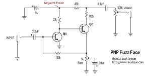
Here's the approach that I usually use for PNP Fuzz Faces these days. It takes +9v power supplies, does not require a voltage inverter/charge pump, and plays nicely with other pedals if they're daisy chained together.
Simple PNP Fuzz Face.png
 
which part?

i said 'if there is +9V going to ground...'

i didn't say '+9V must go to ground'

(just trying to understand where I've got it wrong)
It's possible that I misread what you wrote, but I thought that you were saying that if you used +9v as ground for the circuit, you would also have to use +9v as ground for the audio jack sleeves.
 
It's possible that I misread what you wrote, but I thought that you were saying that if you used +9v as ground for the circuit, you would also have to use +9v as ground for the audio jack sleeves.
nah i meant if +9V is going to ground ground (as per 'vintage' schematics). my bad, i should have been clearer.

tbh i quite like how you depict a 'virtual ground' for the transistors in your design/schematic.
I'm not sure i've seen many schematics that ever bother to differentiate between the two (ground vs. virtual ground)
 
This is not necessarily true. You can use 0v as ground for the jack sleeve, rather than 9v, in the scenario that you outlined and it will work fine.
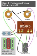
I’m working on a PNP circuit with no led and no dc jack, and followed this setup (below). Wondering if what you’re saying would be advisable, or even possible in this scenario with regards to the audio jacks connecting to “normal” negative ground. I’d love to avoid any issues with NPN pedals elsewhere in the chain.
1753398618083.jpeg
 
I’m working on a PNP circuit with no led and no dc jack, and followed this setup (below). Wondering if what you’re saying would be advisable, or even possible in this scenario with regards to the audio jacks connecting to “normal” negative ground. I’d love to avoid any issues with NPN pedals elsewhere in the chain.
View attachment 99662
Why do you think that it would not be possible to modify this setup to work as I described?
 
Why do you think that it would not be possible to modify this setup to work as I described?
So it would be ok to simply connect In/Out sleeves to the board’s -9v pad (with the battery’s -9v lead) instead of the board’s positive ground pad? In that case it seems like nothing would be connected to the board’s positive ground other than the footswitch… maybe that’s ok?
 
So it would be ok to simply connect In/Out sleeves to the board’s -9v pad (with the battery’s -9v lead) instead of the board’s positive ground pad? In that case it seems like nothing would be connected to the board’s positive ground other than the footswitch… maybe that’s ok?
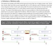
Where are you proposing to connect the positive battery lead in that scenario? You're overthinking this. Just use Figure 6 from that page rather than trying to reinvent the wheel.
 
Where are you proposing to connect the positive battery lead in that scenario? You're overthinking this. Just use Figure 6 from that page rather than trying to reinvent the wheel.
I’m definitely overthinking it, and it turns out I probably don’t have to worry about the audio jack sleeves in a PNP battery-only pedal causing issues with NPN pedals elsewhere in the effects chain; this article helped clear some things up: https://www.amplifiedparts.com/tech-articles/pnp-positive-ground-pedals
1753448156860.jpeg
 
IMG_1861.jpeg

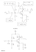
I built this ultra-basic common-emitter amplifier based on Scherz and Monk's excellent 'Practical Electronics for Inventors.'

1753453467935.png

Some parameters: 1mA quiescent current, biased at ~9V, -100 gain in mind. Consequently, it has some slightly quirky values (20V, 74R, and so on).

Currently (!) running it at 18V, subbed 220n for the original 330n and 68R for the 74R, A100k pot as a volume control, and using a 2N1304 Ge transistor (hFE = ~40). I added a 100uF cap and a 100n for power filtering, idea cribbed from our favourite PCB designs. I'm still experimenting with this 'boutique' variant 😁 but it actually sounds quite decent on Tele and P-Bass both as a basic clean preamp.

This might slightly address your original question, @rossbalch, regarding how to deploy low gain Germaniums. While I haven't tried to adjust this for PNP variants, I imagine that one would reverse the power and the associated filter caps. I also have a fair number of low gain PNPs (around 30 or so), so might be worth a shot.

It's refreshing to work with something so simple which does its small signal job with some aplomb.

Incidentally, I'm trusting that publishing this schematic to a closed site does fall under fair use. If not, I'll gladly take it down. It would make this entire post largely pointless but I respect the effort the authors put into this highly recommended book.
 
View attachment 99700

I built this ultra-basic common-emitter amplifier based on Scherz and Monk's excellent 'Practical Electronics for Inventors.'

View attachment 99703

Some parameters: 1mA quiescent current, biased at ~9V, -100 gain in mind. Consequently, it has some slightly quirky values (20V, 74R, and so on).

Currently (!) running it at 18V, subbed 220n for the original 330n and 68R for the 74R, A100k pot as a volume control, and using a 2N1304 Ge transistor (hFE = ~40). I added a 100uF cap and a 100n for power filtering, idea cribbed from our favourite PCB designs. I'm still experimenting with this 'boutique' variant 😁 but it actually sounds quite decent on Tele and P-Bass both as a basic clean preamp.

This might slightly address your original question, @rossbalch, regarding how to deploy low gain Germaniums. While I haven't tried to adjust this for PNP variants, I imagine that one would reverse the power and the associated filter caps. I also have a fair number of low gain PNPs (around 30 or so), so might be worth a shot.

It's refreshing to work with something so simple which does its small signal job with some aplomb.

Incidentally, I'm trusting that publishing this schematic to a closed site does fall under fair use. If not, I'll gladly take it down. It would make this entire post largely pointless but I respect the effort the authors put into this highly recommended book.

Nice! I wonder if bootstrapping and/or negative feedback can help stabilise low Hfe Ge Transistor circuits. I'm curious eventually to make a cascading preamp design similar to the JFET amp simulators and see how it sounds.
 
Nice! I wonder if bootstrapping and/or negative feedback can help stabilise low Hfe Ge Transistor circuits. I'm curious eventually to make a cascading preamp design similar to the JFET amp simulators and see how it sounds.
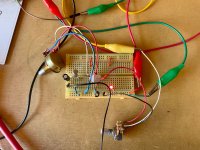
So, I was struck by your original question: how best to use low Beta Germaniums, which has sparked a renewed interest in the circuits I started with some seven years or so ago. I've since breadboarded various PNP Germanium circuits (Joe Gore's Rangemaster variant known as the 'Fiendmaster,' JHS Zonk II). These use between one and two transistors.

IMG_1863.jpeg

For the Zonk mkII I used an OC75 (Beta @ 90) and AC128 (Beta @ 38), both with slight leakage. I like the sound (very 60s rock, Yardbirds et al.). I'm curious to see how a low gain Q1 will affect things. Will keep you posted (if you like).

In any case, thanks for the question, right up my alley since I have a number of low gain PNPs with exactly these specs.
 
Last edited:
So, I was struck by your original question: how best to use low Beta Germaniums, which has sparked a renewed interest in the circuits I started with some seven years or so ago. I've since breadboarded various PNP Germanium circuits (Joe Gore's Rangemaster variant known as the 'Fiendmaster,' JHS Zonk II). These use between one and two transistors.

View attachment 99898

For the Zonk mkII I used an OC75 (Beta @ 90) and AC128 (Beta @ 38), both with slight leakage. I like the sound (very 60s rock, Yardbirds et al.). I'm curious to see how a low gain Q1 will affect things. Will keep you posted (if you like).

In any case, thanks for the question, right up my alley since I have a number of low gain PNPs with exactly these specs.

Yeah, I hate the idea of these devices just rotting away doing nothing. I know we have a tendency match a device to the circuit, and not the other way round, but that seems so wasteful? Surely there are some clever circuit designers around that can make these things useful.
 
Last edited:
The other thing of course is, I'm not married to 9v. Using an external supply and an LT1054 means that anything up to 15v is possible, not sure how that affects things but maybe it will help these lower beta devices be more useful.
 
The other thing of course is, I'm not married to 9v. Using an external supply and an LT1054 means that anything up to 15v is possible, not sure how that affects things but maybe it will help these lower beta devices be more useful.
Go the other way with a Double-AA, eh?

Some of the ol' fuzzircuities used two or even one AA — 3v or 1v5 respectively.


"Maestro Fuzz Tone started as a 3 volt (2 AA batteries) fuzz, then went to 1.5 volt, and then 9 volts (versions FZ-1, FZ-1A, and FZ-1B respectively)."

HEATHKIT TA-28 FUZZ 1v5
Fi-Sonic Fuzz Blender [Maestro FZ-1 variant from down under] 3v


A lot more obscurities are out there, hidden in old electronics magazines, musician magazines etc...


Who needs a knob for "battery-sag" or "voltage starve" when you can just run it right at 1v5 or 3v?
 
Last edited:
Back
Top