These boards are the way. I use them all the time.Excellent read! How did you type that so fast?!?!
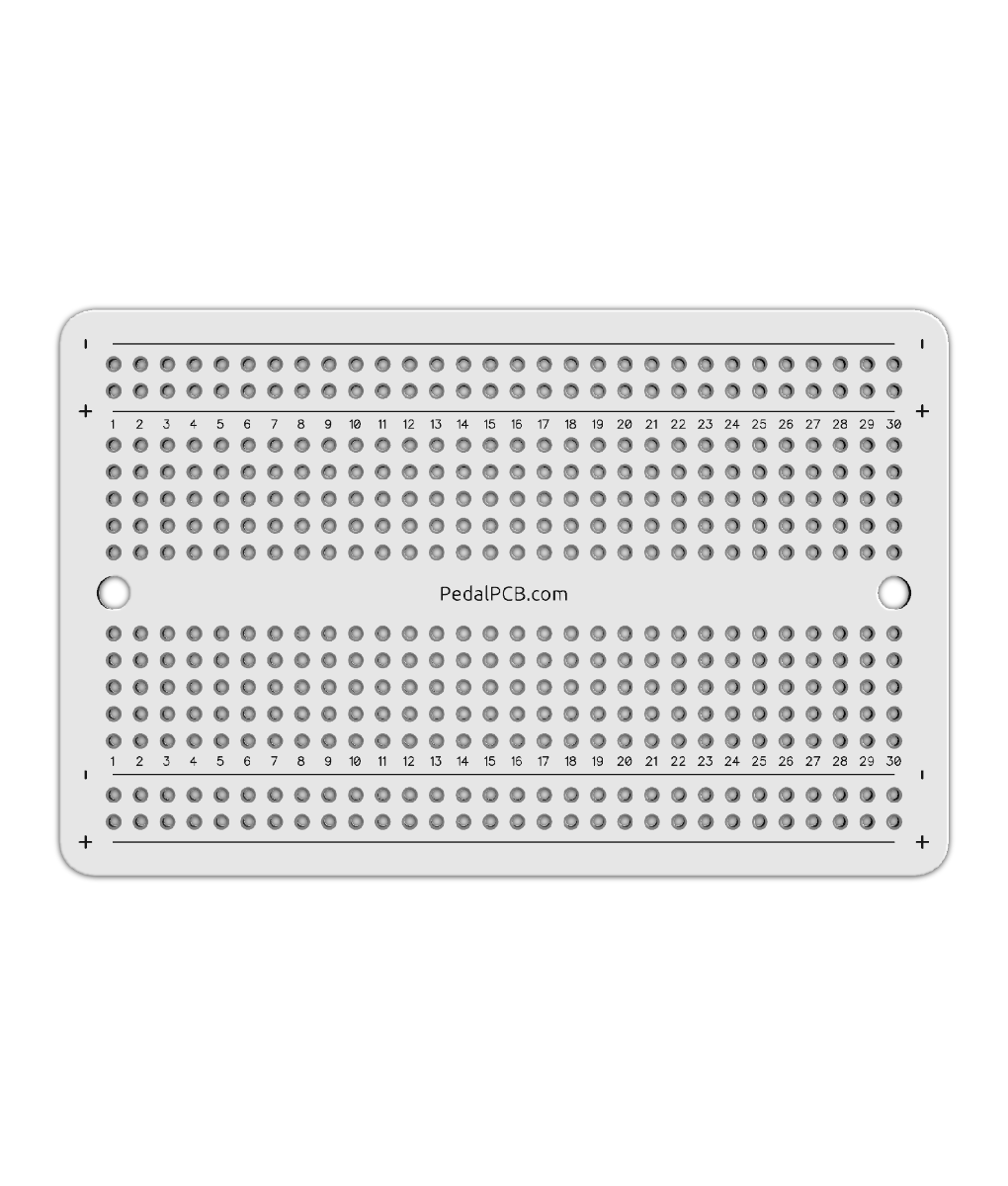
I picked up some stripboard that is laid out like a breadboard with power rails. It's a 1:1 move of components. I still like the "classic" look as well.
View attachment 22388