Wiring question for Paragon

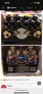
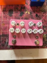
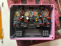
Ok so I’m finally building a Paragon pedal, I’m super excited, currently waiting on parts I didn’t have just on the bench.
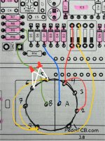
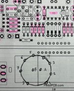
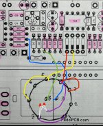
I saw this incredibly clever mod by @jubal81 utilizing a 2p4t rotary switch in place of the pairs of dip switches, so I have my rotary switches and thought I’d just figure it out but it’s breaking my brain, could anyone help me with a diagram of how I can wire them?
Thank yall ahead of time!
-JHK
 
You can use a DPDT on/off/on toggle switch instead of the dip switches. The switches in the KoT allow for 4 possible combinations, but the manual only describes and intends use of 3 of them - soft clipping (one switch up), hard clipping (other switch up), or no clipping (both switches down)

Because of this, you can set the wires that go to the down position of dip switch 1 and 2 to both middle lugs of a DPDT on/off/on toggle switch, and then for the other two wires, the soft clipping goes to the lower lug on one side of the switch, like the bottom left, and then the wire for the second part of the dip switch goes to the opposite lug, say the top right.

In this way when the switch is in the middle position, neither the lower left nor upper right wires are in the circuit, which means no clipping diodes are in effect. When the switch is toggled down, then the wire in the upper right is connected (hard clipping) and when it's toggled up, the wire in the lower left is connected (soft clipping).

It's important that the switch is an ON/OFF/ON, as any other kind of DPDT won't work for this

I explained the details of the dip switch as switch 1 and 2, meaning the first and second sliders of the dip switch as they effect one half of the KoT. The 3rd and 4th sliders control the other half, and are a copy of the first half.

Here's mine to show how I wired my switches
MSslKbB.jpeg


nESqAjb.jpeg
 
Sorry if I’m this comes off as sounding thick, but my intention was to emulate this build.
My confusion is coming from how the 4 terminals attach to the 4 way rotary, the rotary always confuses me I had used one prior to make a multi Cap switcher for my Wah but it’s in replacement for one component, so the mixture of the two switches I think is the hitch is for me.
Thank you for your patience,
-JHK
 

Attachments

  • IMG_6806.png
    IMG_6806.png
    2.1 MB · Views: 4
Oooh ok hold on yes thick as a brick
So,
The 4 positons are
No clip
Soft clip
Hard clip
LED clip
I didn’t realize there was an LED clipper in there!
Love this even more
I’m still a little confused as to how to wire the board to the terminals of the 4 way but I get the 4th position now
 
Back
Top