ianjcunningham
New member
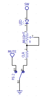
Hi everyone. I have been having limited success wiring up the 3PDT Breakout Board with the LED and trimmer to my own boards. Somehow they work some times but not others and I've pretty much decided I don't know how they work. I took readings in the on/bypassed positions and noticed in on, the SW pad is grounded. I usually put the lead from the 9V jack to that location assuming that's where the LED gets it's power from. Since it goes to ground, I don't understand why it would ever work but here we are. I have the Auditorium test platform that I use before mounting my stuff into an enclosure and the pedal circuit only works if nothing is connected to the SW terminal on that. To summarize, what do I need to connect to the SW terminal on the breakout board, and how does the LED on the breakout board get its power?