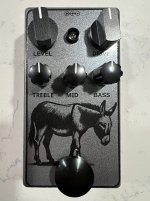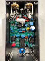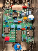
Here's my "xTORTION-10", a lightly-tweaked clone of the Ibanez MT-10 Mostortion.
Background
Back in 2020, one of my earliest - quite possibly my first - non-kit build was the AionFX Quantum, which is Aion's MT-10 Clone. At that time, he didn't offer a kit for this circuit. That build forced me to "remove the training wheels" and graduate to non-kit builds. I actually built two Quantums back then, because I liked the circuit so much. However, the confidence I gained from the successful PCB-only build was a double-edged sword, as it opened up a much bigger world of DIY pedals. Thus, the Quantums were buried by the many builds that followed, and ultimately sold in one of my many decluttering frenzies.
A couple years ago, I revisited PedalPCB's take on this circuit with my Oxide Distortion build. It also fell victim to a decluttering frenzy and was sold.
As evidenced by my most recent build reports, I've developed a personal idiom (like Sir Lancelot) and am slowly building up a portfolio of custom PCBs featuring all my personal preference features: p-mos based reverse-polarity protection, integrated buffered electrical bypass, minimal offboard wiring, etc. Partially due to sentimental feelings towards those old Quantum builds, but also being on a bit of a Nashville-inspired kick (see Nashville Nobility), I felt compelled to do my own MT-10 clone. The cheesy "xTORTION-10" name plays on the original in a couple ways:
The Circuit
My version of this circuit is minimally changed from the stock circuit. I dropped the BJT buffers in favor of opamp buffers (this is part of my idiomatic buffered electrical bypass). Other than making the circuit not faithful to the original, it should be an improvement. Rod Elliott makes a compelling case for opamp-based buffers over discrete implementations.
As mentioned above, I'm using a TL072 instead of the effectively-unobtanium CA3260.
The more interesting tweak I did is adding space for a resistor in series with the clipping diodes (similar to what e.g. the Bluesbreaker does). The stock MT-10 has four 1n4148/1n914 clipping diodes, arranged as two series pairs in opposing polarity. The Aion Quantum adds a clipping selector switch where you can select the original scheme, more distortion/compression via two total clipping diodes, or less distortion/compression via LED diodes. I recall I liked both the LED and stock configs best. But I didn't want a switch (I wanted to use that space for the status LED). So I thought series resistor with the four 1n4148 diodes might be a nice compromise. Right now I've got a 10k resistor in there (by accident, see below) and I think it sounds great - the distortion is much smoother than I remember. I originally planed to use alligator clips to quickly test alternate resistor values (including stock, i.e. 0-ohm), but it sounds so good with the 10k I'm now less motivated to mess with it.
The clipping stage has a 268 Hz low-cut, unlike the Tubescreamer's 720 Hz corner frequency. Thus, the default EQ of the MT-10 is fairly flat. Some might call it transparent. At the time of it's introduction, the passive three-band EQ was a unique feature. The bass is effectively a post-clipping bass cut; the treble has a fairly wide range; the mid actually has a small amount of boost and a fair amount of cut available. The mid control is more of a low-mid control, see its Tone Map.
The Build
I had the enclosure all ready to go. I recycled the Donkey clip art from my Pink Donkey Club build, on a @StompBoxParts "Weston Grey" enclosure. I received the PCB on a day when I didn't have anything going on in the evening. So I was able to knock it out entirely, with enough time left to noodle around a bit before bed... At least that was the plan!
When I powered it up, only bypass (the default state) worked. I couldn't get it to engage: pressing the button did literally nothing: no sound change, no status LED lighting. I knew it wasn't an issue with the microcontroller, as, in order to save time, I stole a programmed PIC12F675 from another build. I also knew the actual switching circuit was good, as it was copy-pasted from that same already-validated build.
Sidebar: while populating the PCB, I noted that I was low on 10k resistors. But that was strange to me, because I was pretty sure I had recently re-ordered 100 10k resistors. I assumed I must have mis-placed the new resistors, and made a mental note to look for them when I was done with the build.
Back to the xTORTION debugging: I probed the circuit a bit, but didn't find any obvious issue. Next I tried bypassing the footswitch entirely, and manually grounding the footswitch MCU pin to simulate a switch press - it worked! That allowed me to focus on the traces and components between the footswitch and the MCU pin. Normally the MCU footswitch pin is held high with a 10k pullup resistor. The footswitch wire has a 1k series resistor, and a 22nF cap that forms an RC circuit that helps debounce the switch, as well as filter out some noise (the firmware does additional debounce and noise mitigation). But the "1k" resistor actually measured 10k: this prevented the footswitch voltage from dropping enough for the MCU to register it as pressed.
So I grabbed a new "1k" resistor from the bag, and it also measured 10k. As it turns out, when I received the 100 10k resistors, I mistakenly put them in the 1k resistor bag. Once I figured that out, I had to replace all the should-be-1k resistors. I had initially planned to use 1k as the clipping diodes series resistor, but that also ended up as 10k; I left it at 10k. But all the other resistors were replaced with the correct value.
This was actually a series of mistakes on my part: I measure resistors before I put them on the board. But in this case, I didn't look closely enough at my DMM when I measured: the numbers were right, but I failed to notice where the decimal landed (e.g. ".998k" vs "9.98k").
Final Words
This is a great circuit, and so far I think the 10k series resistor in the clipping section is a keeper, and it's trivial to jumper if you want to be accurate to the original design. It pairs really well with an ODR-1 circuit (see the Karma Machine Stop for a commercial dual pedal that combines these circuits). The default neutral frequency response, along with the three-band EQ make it fairly versatile: it could definitely be used as a boost, an/or tone-shaper.
As always, I have a few spare PCBs I'm happy to send out.
Background
Back in 2020, one of my earliest - quite possibly my first - non-kit build was the AionFX Quantum, which is Aion's MT-10 Clone. At that time, he didn't offer a kit for this circuit. That build forced me to "remove the training wheels" and graduate to non-kit builds. I actually built two Quantums back then, because I liked the circuit so much. However, the confidence I gained from the successful PCB-only build was a double-edged sword, as it opened up a much bigger world of DIY pedals. Thus, the Quantums were buried by the many builds that followed, and ultimately sold in one of my many decluttering frenzies.
A couple years ago, I revisited PedalPCB's take on this circuit with my Oxide Distortion build. It also fell victim to a decluttering frenzy and was sold.
As evidenced by my most recent build reports, I've developed a personal idiom (like Sir Lancelot) and am slowly building up a portfolio of custom PCBs featuring all my personal preference features: p-mos based reverse-polarity protection, integrated buffered electrical bypass, minimal offboard wiring, etc. Partially due to sentimental feelings towards those old Quantum builds, but also being on a bit of a Nashville-inspired kick (see Nashville Nobility), I felt compelled to do my own MT-10 clone. The cheesy "xTORTION-10" name plays on the original in a couple ways:
- I just did a quick check on Reverb, an original MT-10 will set you back over $700; that's "extortion" in my opinion
- Presumably, the "Mostortion" name was based on the mostfet-input CA3260 opamp used in the original. The CA3260 is out-of-production, and finding an authentic one is now very hard/impossible. I'm using a TL072, which has JFET inputs, so I could call it "J-tortion" or maybe "Fettortion". But the opamp actually doesn't contribute significantly to the sound, so you could also use, for example, a BJT-input RC4558, which would make it a "BJTtortion". See where this is going? Since you can use just about any dual-opamp, I replaced the "MOS" with "x". I tacked on the "-10" as an homage to the "MT10" product ID.
The Circuit
My version of this circuit is minimally changed from the stock circuit. I dropped the BJT buffers in favor of opamp buffers (this is part of my idiomatic buffered electrical bypass). Other than making the circuit not faithful to the original, it should be an improvement. Rod Elliott makes a compelling case for opamp-based buffers over discrete implementations.
As mentioned above, I'm using a TL072 instead of the effectively-unobtanium CA3260.
The more interesting tweak I did is adding space for a resistor in series with the clipping diodes (similar to what e.g. the Bluesbreaker does). The stock MT-10 has four 1n4148/1n914 clipping diodes, arranged as two series pairs in opposing polarity. The Aion Quantum adds a clipping selector switch where you can select the original scheme, more distortion/compression via two total clipping diodes, or less distortion/compression via LED diodes. I recall I liked both the LED and stock configs best. But I didn't want a switch (I wanted to use that space for the status LED). So I thought series resistor with the four 1n4148 diodes might be a nice compromise. Right now I've got a 10k resistor in there (by accident, see below) and I think it sounds great - the distortion is much smoother than I remember. I originally planed to use alligator clips to quickly test alternate resistor values (including stock, i.e. 0-ohm), but it sounds so good with the 10k I'm now less motivated to mess with it.
The clipping stage has a 268 Hz low-cut, unlike the Tubescreamer's 720 Hz corner frequency. Thus, the default EQ of the MT-10 is fairly flat. Some might call it transparent. At the time of it's introduction, the passive three-band EQ was a unique feature. The bass is effectively a post-clipping bass cut; the treble has a fairly wide range; the mid actually has a small amount of boost and a fair amount of cut available. The mid control is more of a low-mid control, see its Tone Map.
The Build
I had the enclosure all ready to go. I recycled the Donkey clip art from my Pink Donkey Club build, on a @StompBoxParts "Weston Grey" enclosure. I received the PCB on a day when I didn't have anything going on in the evening. So I was able to knock it out entirely, with enough time left to noodle around a bit before bed... At least that was the plan!
When I powered it up, only bypass (the default state) worked. I couldn't get it to engage: pressing the button did literally nothing: no sound change, no status LED lighting. I knew it wasn't an issue with the microcontroller, as, in order to save time, I stole a programmed PIC12F675 from another build. I also knew the actual switching circuit was good, as it was copy-pasted from that same already-validated build.
Sidebar: while populating the PCB, I noted that I was low on 10k resistors. But that was strange to me, because I was pretty sure I had recently re-ordered 100 10k resistors. I assumed I must have mis-placed the new resistors, and made a mental note to look for them when I was done with the build.
Back to the xTORTION debugging: I probed the circuit a bit, but didn't find any obvious issue. Next I tried bypassing the footswitch entirely, and manually grounding the footswitch MCU pin to simulate a switch press - it worked! That allowed me to focus on the traces and components between the footswitch and the MCU pin. Normally the MCU footswitch pin is held high with a 10k pullup resistor. The footswitch wire has a 1k series resistor, and a 22nF cap that forms an RC circuit that helps debounce the switch, as well as filter out some noise (the firmware does additional debounce and noise mitigation). But the "1k" resistor actually measured 10k: this prevented the footswitch voltage from dropping enough for the MCU to register it as pressed.
So I grabbed a new "1k" resistor from the bag, and it also measured 10k. As it turns out, when I received the 100 10k resistors, I mistakenly put them in the 1k resistor bag. Once I figured that out, I had to replace all the should-be-1k resistors. I had initially planned to use 1k as the clipping diodes series resistor, but that also ended up as 10k; I left it at 10k. But all the other resistors were replaced with the correct value.
This was actually a series of mistakes on my part: I measure resistors before I put them on the board. But in this case, I didn't look closely enough at my DMM when I measured: the numbers were right, but I failed to notice where the decimal landed (e.g. ".998k" vs "9.98k").
Final Words
This is a great circuit, and so far I think the 10k series resistor in the clipping section is a keeper, and it's trivial to jumper if you want to be accurate to the original design. It pairs really well with an ODR-1 circuit (see the Karma Machine Stop for a commercial dual pedal that combines these circuits). The default neutral frequency response, along with the three-band EQ make it fairly versatile: it could definitely be used as a boost, an/or tone-shaper.
As always, I have a few spare PCBs I'm happy to send out.