PedalBuilder
Well-known member
Another Tone Bender that is more of a Big Muff. Take the first two stages of a Colorsound Supa Tone Bender, add a third stage that is part Big Muff and part Tone Bender Mk. III (with a Zener diode rather than the customary 10k/10k voltage divider), stick a weird variant of a Big Muff Tone Stack on the end, and this is what you get:

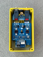
In my view, it's a Muff. When I designed the PCB, I started off with my standard Big Muff PCB, made a few changes, and had a final design in about 20 minutes. It looks like Macari's/Sola Sound also thinks it's a Muff, given that they build it on a Big Muff (or maybe dual purpose) PCB:

When I breadboarded the circuit, I wasn't thrilled with the functionality of the gain control. So I used the handy search feature, and found that @Chuck D. Bones had some suggested mods to the circuit. (Weirdly, I can't find that thread any more, even though I looked at it a day or two ago. I swear that I'm not imagining it!)
I implemented most of Chuck's suggestions at least in spirit. I didn't have a C250k for the gain pot, so I used an A250k wired upside down and backwards (picture below), which behaves essentially identically. Rather than omit R6 and ruin the symmetry of the layout, I used a 10M, which is close enough to my ears. C5 uses a 150nF capacitor on top of the PCB and a 22µ electrolytic tacked onto the back. I substituted a 680nF for C8 because I had extras, the sounded the same, and they fit the footprint better than the 470nF caps that I had on hand.
Transistors are a BC109 (hFE 245) for Q1, BC109C (hFE 473) for Q2, and a 2SD77 that I got courtesy of @fig for Q3 (hFE 58, leakage 85). Q1 collector is at 4.31v, Q2 collector is at 4.24v, and Q3 collector is at 2.7v with VCC = 9.27v. The diode is a D9L that I got from Pedalhacker back in 2018. I tried some other diodes (D9D, D9E, D18), but the D9L one biased Q3 best.
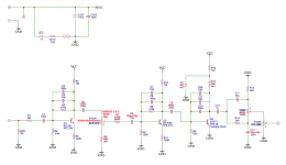
The mods are detailed in the schematic.
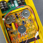
Here's how I wired the Fuzz (now Balance) control, with a 4.7nF cap between lugs 1 and 2:

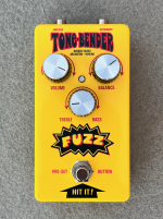
And lastly, the enclosure from the outside, a Tayda yellow 125B UV printed with a double pass of white and matte varnish:

In my view, it's a Muff. When I designed the PCB, I started off with my standard Big Muff PCB, made a few changes, and had a final design in about 20 minutes. It looks like Macari's/Sola Sound also thinks it's a Muff, given that they build it on a Big Muff (or maybe dual purpose) PCB:
When I breadboarded the circuit, I wasn't thrilled with the functionality of the gain control. So I used the handy search feature, and found that @Chuck D. Bones had some suggested mods to the circuit. (Weirdly, I can't find that thread any more, even though I looked at it a day or two ago. I swear that I'm not imagining it!)
I implemented most of Chuck's suggestions at least in spirit. I didn't have a C250k for the gain pot, so I used an A250k wired upside down and backwards (picture below), which behaves essentially identically. Rather than omit R6 and ruin the symmetry of the layout, I used a 10M, which is close enough to my ears. C5 uses a 150nF capacitor on top of the PCB and a 22µ electrolytic tacked onto the back. I substituted a 680nF for C8 because I had extras, the sounded the same, and they fit the footprint better than the 470nF caps that I had on hand.
Transistors are a BC109 (hFE 245) for Q1, BC109C (hFE 473) for Q2, and a 2SD77 that I got courtesy of @fig for Q3 (hFE 58, leakage 85). Q1 collector is at 4.31v, Q2 collector is at 4.24v, and Q3 collector is at 2.7v with VCC = 9.27v. The diode is a D9L that I got from Pedalhacker back in 2018. I tried some other diodes (D9D, D9E, D18), but the D9L one biased Q3 best.
The mods are detailed in the schematic.
Here's how I wired the Fuzz (now Balance) control, with a 4.7nF cap between lugs 1 and 2:
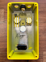
And lastly, the enclosure from the outside, a Tayda yellow 125B UV printed with a double pass of white and matte varnish:
Last edited:

