Inside a Vactrol (no surprises)

phi1

Well-known member
Building a pair of harmonic tremolos (similar to the Cardinal Tremolo V2 with a couple tweaks). On one pedal the bass side of the harmonic trem was really weak.

I confirmed all the parts and determined it was the Vactrol (xVive VTL5C1) acting up.

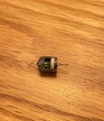
I decided to cut it open just to look. I knew it was just an LED and LDR in a plastic package. I didn’t realize the LED was green (I was picturing red for some reason). Seems like the LED might be too dim.

Anyway, disappointing but so it goes, hopefully a new vactrol will get the circuit sounding as it should.

The original cardinal tremolo designer (Jon Patton) recommends the vactrol over the diy LED/LDR combo. But if I build one of these circuits again, I may attempt led-ldr with heat shrink so the two don’t interact.
Any thoughts welcome. Just thought some people might like seeing it cut open.
 

Attachments

  • BFE9CDFB-CF3D-4875-B4B8-228B19DAC8C0.jpeg
    BFE9CDFB-CF3D-4875-B4B8-228B19DAC8C0.jpeg
    465.5 KB · Views: 84
... if I build one of these circuits again, I may attempt led-ldr with heat shrink so the two don’t interact.
Any thoughts welcome. Just thought some people might like seeing it cut open.

Thanks for sacrificing your xVive VTL5C1 for Pedal-Science.

As Jimilee noted, durned little thangs 're 'spensive.


I'm not gettin' what you mean by "...so the two don't interact..." — the whole point of an LED/LDR combo is for the two to interact.

N'est-ce pas? 🤔


At any rate, lookin' at how simple the xVive VTL5C1 is (thanks again for the cutaway xray vision specs), I'm thinking it'd be cheaper to just build one — any way to determine the cashy-critter's LDR-type/spec?

X-Ray_Spex.jpg
 
Sorry for the confusion in wording…

I don’t want the two sets of LED/LDR to interact (one for bass patch, one for treble in the harmonic tremolo). Like bleed from one LED picked up by the other LDR.


The pedalpcb pendulum pcb is laid out such that the two sets are on opposite sides of the board, so it works out well enough without any covering
 
Last edited:
The vtl5c1 specs are written as current in (to drive the led) correlated to resistance. Typical LDR specs correlate the luminance to the resistance. So, it’s not a direct correlation to compare the specs. The LED datasheet may give a current to luminance emitted correlation, I’d be curious though given the spacing and what not if the led spec emitted luminance is exactly what lands on the ldr.

Personally, I may just go for the “try and see how well I can match the sound” approach
 
Do they touch the led all the way to the LDR? Kinda looks like it.
yeah it does touch. I wonder how that affects the evenness of the distribution of light on the LDR surface, or if that matters. Maybe that's just the easiest way to make them consistent spacing, or smallest form factor.

When I've put together LED/LDR combos, it's depended how close I put them. Typically probably about 1mm. I know for the Pendulum I had to adjust the spacing some to get the 2 channels (lows and highs) to balance well.
 
Back
Top