Big Muff Pi on a breadboard - passes signal until power is applied.

ibanez flanger

New member
Hiyas,

Total noob looking for some help. Not sure if I deserve any....

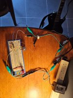
With no power connected, I get a clean signal passing through.

When I plug the 9v (wall wart PSU) in, I get 1-2 seconds of total silence then a constant tick-tick-tick sound, maybe 10-12 ticks per second.

Same results with a 9v battery.

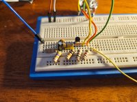
With no power connected, I went through and tested each component and although some had some variations, I thought they were possibly close enough to suffice?

But I don't really know how to test them with power connected, or really where to start troubleshooting.

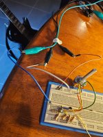
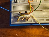
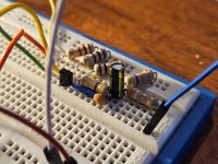
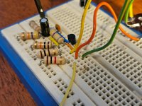
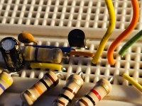
Apologies if my photos are not adequate. Happy to take some more if requested.

If I ever get to another pcb, I will replace the resistors with the blue ones people say are better.

1764240408433.png

20251127_214804.jpg 20251127_214817.jpg 20251127_214842.jpg 20251127_214856.jpg 20251127_214917.jpg 20251127_214925.jpg 20251127_214952.jpg 20251127_214958.jpg 20251127_215006.jpg 20251127_215012.jpg 20251127_204004.jpg
 
When you breadboard it, you should build it in stages. Build the input booster stage, then check it works. Then move onto half of the clipping amplifier, check it works, then move to the next.
Hi neiltheseal. Thanks for the reply.

Probably an obvious question but what sounds should I hear after each stage? I did that after the input booster. Just got the same low volume clean tone, and the pot didn't seem to behave like I thought it would increasing volume when turning clockwise. I fact it seemed reverse if anything, but swapping pins did not fix it.

I got some kind of distortion after the clipping stages too, bt I had to strum quite hard to get it.

Also, very annoyingly, but intermittently, I get zero signal. I'm just not trusting the pins in the breadboard sockets are a reliably transporting current.
 
Well, for one, your clipping diodes are parallel, they need to be anti-parallel.

Parallel:


Anti-parallel:


Just turn one of each set around, doesn't matter which one of each pair:


However, I don't think the diodes alone are responsible for the ticking and lack of desired Muffy Fuzz.


Suggestion:
In addition to Neil's suggestion to build one section of the circuit at a time, I'll also suggest simplifying the build as much as possible; You've got a lot of jumpers, such as components stretched on one axis with jumpers when you could rearrange the layout to get rid of a jumper and just have the component connect directly to the row/column of the next component to be connected.

The most important thing is whether it makes sense to you, and if it does stick with that — but I still encourage to experiment with streamlining your layouts in future. For example, I find this way of breadboarding defeats several principle-reasons for breadboarding — simplicity being key and breadboards' built-in links/jumpers — why so many jumpers and spreading it across THREE breadboards? C'EST BIZARRE! :

BREADBOARD%2BDeadastronaut%2BSpace%2BPatrol.png

I will say it's easy to follow the signal path on the above layout.


I would split your circuit as per the schematic you posted, save I would split the two clipping sections as well, a total of 5 distinct sections with plenty of space between them and a jumper to connect each section — I'd even go so far as to use a specific colour of jumper for the splits and use only that one colour for splits (4 jumpers total), if there's enough jumpers for building it that way.


In the first link below, you'll find a Quarantine Fuzz I breadboarded. I'm not the greatest breadboarder out there, but in the space of half a breadboard (no clipping diodes nor clipping caps in the Quarantine), I've got what I think is a reasonably efficient layout.
I could easily add those aforementioned omitted components to make it a full on Muff without cluttering it up, too.

 
Well, for one, your clipping diodes are parallel, they need to be anti-parallel.

Parallel:


Anti-parallel:


Just turn one of each set around, doesn't matter which one of each pair:


However, I don't think the diodes alone are responsible for the ticking and lack of desired Muffy Fuzz.


Suggestion:
In addition to Neil's suggestion to do build one section of the circuit at a time, I'll also suggest simplifying the build as much as possible; You've got a lot of jumpers, such as components stretched on one axis with jumpers when you could rearrange the layout to get rid of a jumper and just have the component connect directly to the row/column of the next component to be connected.

The most important thing is whether it makes sense to you, and if it does stick with that — but I still encourage to experiment with streamlining your layouts in future. For example, I find this way of breadboarding defeats several principle-reasons for breadboarding — simplicity being key and breadboards' built-in links/jumpers — why so many jumpers and spreading it across THREE breadboards? C'EST BIZARRE! :

BREADBOARD%2BDeadastronaut%2BSpace%2BPatrol.png

I will say it's easy to follow the signal path on the above layout.


I would split your circuit as per the schematic you posted, save I would split the two clipping sections as well, a total of 5 distinct sections with plenty of space between them and a jumper to connect each section — I'd even go so far as to use a specific colour of jumper for the splits and use only that one colour for splits (4 jumpers total), if there's enough jumpers for building it that way.


In the first link below, you'll find a Quarantine Fuzz I breadboarded. I'm not the greatest breadboarder out there, but in the space of half a breadboard (no clipping diodes nor clipping caps in the Quarantine), I've got what I think is a reasonably efficient layout.
I could easily add those aforementioned omitted components to make it a full on Muff without cluttering it up, too.

Thanks Feral Feline. More great advice and tips.

I've built and rebuilt probably 20 times trying to simplify it. Good to know I need to do it again.

One reason for the jumpers was to try to physically distance components which helps me trace it. But yeah I probably have too many.

Love your suggestions to split it further and colour code. Simple but very logical.

The diodes...I will do as you suggest but aren't they both depicted facing the same way on the circuit diagram?
 
Well, for one, your clipping diodes are parallel, they need to be anti-parallel.

Parallel:


Anti-parallel:


Just turn one of each set around, doesn't matter which one of each pair:


However, I don't think the diodes alone are responsible for the ticking and lack of desired Muffy Fuzz.


Suggestion:
In addition to Neil's suggestion to build one section of the circuit at a time, I'll also suggest simplifying the build as much as possible; You've got a lot of jumpers, such as components stretched on one axis with jumpers when you could rearrange the layout to get rid of a jumper and just have the component connect directly to the row/column of the next component to be connected.

The most important thing is whether it makes sense to you, and if it does stick with that — but I still encourage to experiment with streamlining your layouts in future. For example, I find this way of breadboarding defeats several principle-reasons for breadboarding — simplicity being key and breadboards' built-in links/jumpers — why so many jumpers and spreading it across THREE breadboards? C'EST BIZARRE! :

BREADBOARD%2BDeadastronaut%2BSpace%2BPatrol.png

I will say it's easy to follow the signal path on the above layout.


I would split your circuit as per the schematic you posted, save I would split the two clipping sections as well, a total of 5 distinct sections with plenty of space between them and a jumper to connect each section — I'd even go so far as to use a specific colour of jumper for the splits and use only that one colour for splits (4 jumpers total), if there's enough jumpers for building it that way.


In the first link below, you'll find a Quarantine Fuzz I breadboarded. I'm not the greatest breadboarder out there, but in the space of half a breadboard (no clipping diodes nor clipping caps in the Quarantine), I've got what I think is a reasonably efficient layout.
I could easily add those aforementioned omitted components to make it a full on Muff without cluttering it up, too.

Oh ignore my diode question. Just rechecked the circuit....
 
If it's any comfort, I'm getting NOTHING with a Bosstone variant I recently breadboarded. Okay, not nothing, but just static-y-crackley-crapola.
Probably/Arguably an even simpler circuit than the Muff. I hate troubleshooting, 'cause I need to do too much of it — so you'd think I'd be good at it by now. 😼 I'll have to look at that tonight, I'm running out of time, it's a build for a friend of a friend — Gristmas looms nigh.

Best of luck getting your board sorted.
 
Hi neiltheseal. Thanks for the reply.

Probably an obvious question but what sounds should I hear after each stage? I did that after the input booster. Just got the same low volume clean tone, and the pot didn't seem to behave like I thought it would increasing volume when turning clockwise. I fact it seemed reverse if anything, but swapping pins did not fix it.

I got some kind of distortion after the clipping stages too, bt I had to strum quite hard to get it.

Also, very annoyingly, but intermittently, I get zero signal. I'm just not trusting the pins in the breadboard sockets are a reliably transporting current.
Each stage is different. The input booster stage just makes the signal really loud. If yours is quiet then your problem is here.

Clipping stages will distort.

It sounds like your pot is wired backwards, that's not really a problem.

Sounds like you have a cheap breadboward if the sound cuts out intermittently. You are better off buying a decent one for this reason. Bus Board is a good one I use. I did the same thing that you did when I started. So glad I threw out the cheap breadboards and bought better ones.
 
What transistors are you using by the way? They might have the wrong pinout which could be your problem
2n5088's from Mouser. I checked the datasheet for the pinouts. Wasn't completely clear to me which was which...they listed emitter as 1, base 2 and collector 3 followed but there's no image with the numbers pointing to the pins. The main image had it oriented flat side ot so I just assumed it was numbered 1, 2, 3 left to right.
 
2n5088's from Mouser. I checked the datasheet for the pinouts. Wasn't completely clear to me which was which...they listed emitter as 1, base 2 and collector 3 followed but there's no image with the numbers pointing to the pins. The main image had it oriented flat side ot so I just assumed it was numbered 1, 2, 3 left to right.
Try flipping the transistors the other way. I have never seen a 5088 with that pinout (you might have it right, I just have not seen one). Usually the emitter is the leftmost pin when the flat side is facing you.
 
Try flipping the transistors the other way. I have never seen a 5088 with that pinout (you might have it right, I just have not seen one). Usually the emitter is the leftmost pin when the flat side is facing you.
I think emitter left, flat side facing is what I'm already doing?

Anyway, I have just rebuilt the circuit on a better breadboard and, unsurprisingly, am getting better results. You sir have probably saved me much pain. Many thanks for that.

Would appreciate any one taking a look at the new layout too if possible?

I've also taken @Feral Feline 's advice to split it into sections so it's just the input booster stage for now.

From one round of testing, results are.... interesting.

I need to completely re-review and retest because they're not really making sense. Ok, just did it and it still makes no sense...

So I now get an increase in clean tone by turning the pot clockwise. Win. Thanks for all the assistance.

But I seem to be getting that same result regardless of the orientation of the 2n5088, or whether power is applied or not!

With no power applied, I strum the guitar and remove the 2n5088...and I can still hear audio. Seems obvious that either the signal isn't making it to the transistor or it's faulty but I have swapped it out and I still have the same results.

Then I realised I didn't know what results I should expect from an input booster stage when power is applied?
 

Attachments

  • 20251201_192703.jpg
    20251201_192703.jpg
    628 KB · Views: 4
  • 20251201_192734.jpg
    20251201_192734.jpg
    688 KB · Views: 4
  • 20251201_192747.jpg
    20251201_192747.jpg
    569.3 KB · Views: 5
  • 20251201_192801.jpg
    20251201_192801.jpg
    515.7 KB · Views: 5
  • 20251201_192806.jpg
    20251201_192806.jpg
    527.9 KB · Views: 5
  • 20251201_192824.jpg
    20251201_192824.jpg
    479.1 KB · Views: 5
  • 20251201_192839.jpg
    20251201_192839.jpg
    490.9 KB · Views: 5
  • 20251201_192850.jpg
    20251201_192850.jpg
    484.2 KB · Views: 4
A lot of good breadboard advice on here. Most important one is to build a circuit and test it in stages, which you have. Your first stage is nothing more than a booster and should be louder than your input signal especially with the knob cranked.

A few observations based on the pics in post #14. This is also assuming power is on the inner rail and ground is the outer. I will reference the ref des of the Muffin Fuzz schematic:

-Your power connections (+9V and ground) are plugged into the same power rail. Nevermind. Both audio jacks are grounded in the same place. It may be worth your time to make a test box so all you'll have to do connect power, ground, IN, and OUT directly from the box to the breadboard. It's a useful tool for breadboarding, stripboard circuits, and PCBs before boxing them up.

-C1 doesn't have to be an electolytic. It's just the way the circuit is drawn. A box cap would be fine here. The orientation of electros matters in certain circuits.

-C3 is missing from your circuit. This blocks unwanted DC voltage from creeping into the next circuit block. In this circuit it also acts in tandem with the SUSTAIN pot and R6 as a high pass filter. The sustain pot acts as a voltage divider and throws unwanted signal to ground through R6.

-The sustain pot is not connected to the collector of your transistor if it is indeed a 5088 with the pinout noted above from Feral Feline. You have it wired to the emitter which won't have the amplification properties you want.

-R3 should connect from the collector to base of Q1. You have it wired from emitter to base. R3 and R2 work together to properly bias Q1 at the base to properly "turn on" the transistor with the proper voltage.

-C2 is also wired incorrectly. It should be like R3 in going from collector to base.

-R4 should be connected from VCC to Q1-Collector. It looks like you have it connected to ground. It is also good practice to throw a higher value electro cap in the power rails (mind the orientation) to provide "clean" power and reduce noise.

My advice is to start the circuit block over and spread out a bit. It makes troubleshooting a bit easier.

This reminds me to probably make a BMP breadboard tutorial.
Thanks BuddytheReow.

A few questions...

C1 - drawn with polarity but, it doesn't matter? Why would someone do that?

C3 and R6 - not on my drawing...

I mean no wonder it's not working if it's missing critical components or is mis-drawing others!

What is a "ref des" (I assume reference design? ) and where do I go to find it?

What is BMP referring to?

Not trusting it now but...
Currently, my first stage is louder when cranked, but that is regardless of whether power is connected or not.

So the question might be moot until I fix all the problems you've pointed to, but what should I expect when I connect the power?

I was subconsciously expecting "much louder" as the answer, but I realised that was just an assumption, and I really had no idea what should happen.
 
-Certain designers like to keep the polarity of the cap in question, regardless of the cap type. Chuck's schematics (check out his boneyard posts) will consider polarity for all capacitors he uses. Polarity should normally be considered when you're using an electrolytic cap. Unless told otherwise an electro will have a value of 1uf or higher. But, putting your electros in here won't make a bit of difference sonically as long as you have the correct orientation.

"Ref des" refers to reference designation in a circuit. Instead of saying a "1M Ohm pull down resistor right after input" the schematic writer can simply call it R1 and will need to refer to the schematic in question.

The schematic I am referring to is the PPCB Muffin Fuzz found on the shop website, which I assumed you were using being here on this forum.
1764626012413.png

BMP = Big Muff Pi

Once you've got this first stage hooked up correctly (up through the sustain pot) you'll have a generic amplifier with the volume knob being an attenuator. If R6 (see schematic above) wasn't there and the Sustain pot was connect directly to ground you would have the ability to have no sound come through if the knob was fully counter clockwise.

The booster stage, and for that matter, this whole circuit is nothing more than 4 LPB-1 circuits with some slight tweaks plus a tone section. If you're interested in the basics of the LPB-1 I would suggest the below reading. There are also other good sources of circuit analysis for the Big Muff and LPB-1.

For that matter, the Test Kitchen forum has some great breadboard and circuit knowledge in there. It's worth checking out.

 
Last edited:
Back
Top