
When we say clock it's a bit of a generalisation as there's several components to it... a modulation element, an oscillator and usually, a flip flop to provide both phases i.e. the tick and tock of a clock.
The square wave 'clock' directly connecting to the BBD isn't what changes the sound, assuming it's nice and clean, it always just puts out a square wave to tell the BBD at what speed to pass its buckets.
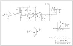
In this case the 4007 is configured as a simple two inverter oscillator with the timing resistor being varied by an LDR to modulate it and the 4049 is inverting its output to provide both the necessary phases.
If you look at the MN3102 datasheet, an example oscillation circuit is given, it's the same oscillator as here, just a bit meatier followed by a flip flop and some waveshaping.
It's how it's modulated that's important... although some chips are beefier than others which can impact sweep range and a flip flop is going to give a cleaner square than something simple like this configuration and the MN series has said built in wave forming business which offers some benefits yada-yada caveats.
In the CE-2, the oscillators timing is modulated by an astable formed with the transistor, in the small clone a diode's used a dirty variable resistor in an A/DA flanger the CD4007 is just using a MOSFET from inside the chip as a much better variable resistor to modulate the CD4047's oscillator but all these methods of modulation have their own linearities and such which does start to impact the sound of the modulation.
Here, you have an LDR as your modulation element, as long as that LED/LDR pair are providing the same sweep range on whatever oscillator you plonk them on to vary, you'll get the same the result out, only you're going to add a flip flop for a nice clean square wave so the BBD is happier.
Put another way, if you added the wave forming from the MN310X series to a CD4047 with some additional circuitry and were getting the exact same square wave timing there'd be no audible difference between them in a DM-2.
Edit: But yes, quality of the clock does have some impact, although if you're talking about the difference between a flip flop output and one with waveforming the benefit is getting smaller, if you're talking about one with sloppy edges, you'll start to hear it in poor performance from the BBD.
The square wave 'clock' directly connecting to the BBD isn't what changes the sound, assuming it's nice and clean, it always just puts out a square wave to tell the BBD at what speed to pass its buckets.
In this case the 4007 is configured as a simple two inverter oscillator with the timing resistor being varied by an LDR to modulate it and the 4049 is inverting its output to provide both the necessary phases.
If you look at the MN3102 datasheet, an example oscillation circuit is given, it's the same oscillator as here, just a bit meatier followed by a flip flop and some waveshaping.
It's how it's modulated that's important... although some chips are beefier than others which can impact sweep range and a flip flop is going to give a cleaner square than something simple like this configuration and the MN series has said built in wave forming business which offers some benefits yada-yada caveats.
In the CE-2, the oscillators timing is modulated by an astable formed with the transistor, in the small clone a diode's used a dirty variable resistor in an A/DA flanger the CD4007 is just using a MOSFET from inside the chip as a much better variable resistor to modulate the CD4047's oscillator but all these methods of modulation have their own linearities and such which does start to impact the sound of the modulation.
Here, you have an LDR as your modulation element, as long as that LED/LDR pair are providing the same sweep range on whatever oscillator you plonk them on to vary, you'll get the same the result out, only you're going to add a flip flop for a nice clean square wave so the BBD is happier.
Put another way, if you added the wave forming from the MN310X series to a CD4047 with some additional circuitry and were getting the exact same square wave timing there'd be no audible difference between them in a DM-2.
Edit: But yes, quality of the clock does have some impact, although if you're talking about the difference between a flip flop output and one with waveforming the benefit is getting smaller, if you're talking about one with sloppy edges, you'll start to hear it in poor performance from the BBD.
Last edited:

")