Hey everyone, I'm a little stumped with this issue and I'm hoping to get some help. First time building an Aion pedal, the VH drive (https://aionfx.com/app/files/docs/vh_drive_channel_documentation.pdf) and it worked for a few minutes, but then it got noisier and noisier until after a couple of minutes where now it's all noise that's coming out of it even with nothing plugged in.
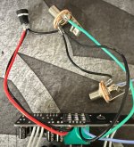
The one thing that's obvious that I screwed up is that I mounted the foot switch on the wrong side of the board. I'll have to fix it before I box it, but I don't think it would cause any issues while I'm testing it (please let me know if I'm wrong).
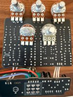
The voltage coming out of the power board look good, +/- 15v and going to each IC as expected in pins 4 and 8. The one odd thing I see is that pins 1, 2, and 3 of IC 1 have some negative voltage (-8v to -12v) and I can't explain that but I'm also not sure it would cause the issue here.
In the screenshot, IC1 is removed while I was testing some voltages only.
The one thing that's obvious that I screwed up is that I mounted the foot switch on the wrong side of the board. I'll have to fix it before I box it, but I don't think it would cause any issues while I'm testing it (please let me know if I'm wrong).
The voltage coming out of the power board look good, +/- 15v and going to each IC as expected in pins 4 and 8. The one odd thing I see is that pins 1, 2, and 3 of IC 1 have some negative voltage (-8v to -12v) and I can't explain that but I'm also not sure it would cause the issue here.
In the screenshot, IC1 is removed while I was testing some voltages only.