Hydra delay - no signal

tpmc12

New member
Hello everyone,

Finishing off the hydra delay. When I go to test it I’m not getting any signal when the pedal is off or on. The led does turn on.

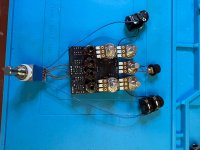
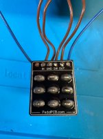
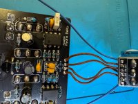
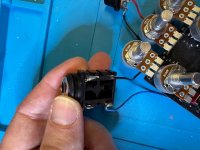
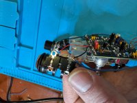
Below are the pictures with a focus on my off board wiring because that is where I suspect the issue is. The solder joints for the footswitch daughter board are very dull - my first though is to reflow all of those in case one of them is cold.

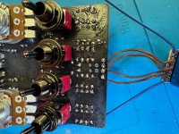
It’s also my first time using these enclosed jacks.
 

Attachments

  • IMG_2674.jpeg
    IMG_2674.jpeg
    653.4 KB · Views: 20
  • IMG_2673.jpeg
    IMG_2673.jpeg
    469.9 KB · Views: 20
  • IMG_2684.jpeg
    IMG_2684.jpeg
    785.7 KB · Views: 13
  • IMG_2682.jpeg
    IMG_2682.jpeg
    870.3 KB · Views: 14
  • IMG_2681.jpeg
    IMG_2681.jpeg
    682 KB · Views: 15
  • IMG_2679.jpeg
    IMG_2679.jpeg
    594.6 KB · Views: 20
That crystal oscillator look a little different than the ones I usually see used. The part number looks pretty clear but I couldn’t find it. Is it 32.768 kHz?
 
Lots of flux, hard to tell if there are solder balls/bridges causing shorts. I would clean the board to make sure there aren't any shorts due to solder bridges.
 
Could use a clean with a toothbrush and isopropyl alcohol. I also was wondering with ErikS about that slashy looking line, and make sure there are no solder bridges between pads.

Have you tried each "head" switch? And dimed the knobs? And ensured that the cables are going into the right jacks? I assume you have, but you never do know, especially with myself.
Ive spent way too much time trouble shooting a build where the in was in the our…
 
Thank you for the schematic - I had to push this aside for a bit with work and life generally. But over the weekend I built a simple DIY audio probe and figured out how to use it - took an extra second with the pedal upside down.

Pins 1 and 2 - no signal. Of course 27 and 28 also had no signal.

R3 - Was able to get a signal on both sides of the pcb at both contact points, though my thought is to go in and reflow both joints at R3 after work tonight. My assumption is that I can still get a signal with the probe through a cold solder joint if the probe is making contact with the component lead (which is not properly soldered to the pcb terminal/pad) - is this correct?

Is there anything else I should check based on the symptoms get signal from looper ---> pedal input ---> audio probe at R3 ---> amp but no signal when the audio probe is at pin 1 of the FV1?
 
Last edited:
Thank you for the schematic - I had to push this aside for a bit with work and life generally. But over the weekend I built a simple DIY audio probe and figured out how to use it - took an extra second with the pedal upside down.

Pins 1 and 2 - no signal. Of course 27 and 28 also had no signal.

R3 - Was able to get a signal on both sides of the pcb at both contact points, though my thought is to go in and reflow both joints at R3 after work tonight. My assumption is that I can still get a signal with the probe through a cold solder joint if the probe is making contact with the component lead (which is not properly soldered to the pcb terminal/pad) - is this correct?

Is there anything else I should check based on the symptoms get signal from looper ---> pedal input ---> audio probe at R3 ---> amp but no signal when the audio probe is at pin 1 of the FV1?
ok - reflowed R3 and am now getting signal to pin 1. I am not getting anything out of pin 28. Pin 6 and 8 had 3.3v running to them then my meter ran out of batteries and I called it a night. Should have some more time over the next few days to review the schematic and probe around some more.
 
Back
Top