I'm debugging a Derailer and I must be missing something obvious. Since the board and layout diagram identify parts by value how does one find a specific part on the board when there are multiples of a single value. I think I have an good idea due to proximity to other parts but I can't be certain. For example the schematic indicates a 1M resistor but there are 3 of them on the board.
Thanks
Thanks! I have isolated the problem (loud buzzing) to a section of the schematic, coming off pin 6, but want to make sure before I start replacing parts.
I'm debugging a Derailer and I must be missing something obvious. Since the board and layout diagram identify parts by value how does one find a specific part on the board when there are multiples of a single value. I think I have an good idea due to proximity to other parts but I can't be certain. For example the schematic indicates a 1M resistor but there are 3 of them on the board.
Thanks
Well, apart from spoon-feeding you the refdes, nobody has addressed your question yet:
"how does one find a specific part on the board when there are multiples of a single value?"
Have you got a Digital Multi-Meter (DMM)?
If you don't, you should get one. The cheapest of the cheap may not have a continuity tester, make sure you have one that can test for continuity (often piggybacked on the "diode" setting.
Armed with a DMM and a schematic, you can usually figure out which component is what on a PCB by using the continuity BEEP setting on your DMM and probing to see what each 1M resistor connects to.
I'll label them thusly:
A) 1M
B) 1M
C) 1M
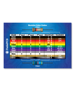
OH, but what if you've already populated the PCB and can't see the silkscreened part value under the part you just soldered in.
Robert's handy Resistor Colour Chart:
Or an online resistor calc such as offered by Digikey.
Using the probes, DMM on continuity check one side of the first 1M, "A", and poke around with the other probe to see what "A"'s connected to — It's connected to the IN pad of the PCB. Check it's right side and poke around some more. Repeat for "B" and "C".
R/SIDE
LEFT CONNECTIONS
RIGHT CONNECTIONS
A 1M
GND
IN / 22n
B 1M
22n / 1k
10n / 1V8 / 4k7 / 2µ2 / 100k / etc
C 1M
ICpin6 / 3k3 / 220p
220p / 100k
Compare all that info in the table above to the schematic:
On the schematic, the 1M connected to IN/C1 must be "A"; it's also the only 1M connected to GND — so A=R1.
"B" has one side that seems to be connected to a LOT of different components, because it is — ie connected to VREF which in turn is connected to a lot of components. The other side of B only connects to two components, so safe to say B=R3.
"C" is the only 1M connected to an IC, and its other connected components confirm C=R12.
This is basic circuit-tracing 101.
If you delve further...
You could see what's connected to what on a mystery PCB (not the Derailer) and with some knowledge/experience about the building blocks of circuits, you can draw your own schematic up — basically a good chunk of what Robert does for a living: tracing circuits to see what components are clumping together and then recognising the building block and drawing it up:
"Oh that's a feedback loop on that IC's op-amp with a passive LPF, followed by an active HPF... yup, yet another YATS to add to the pile."
If you're referring to me, I don't know why.
Sure, I can be a jerk, but who isn't from time to time?
This isn't one of those jerky times.
My previous post answers your OP's question, since I have no idea where you are on your build path.
Perhaps you're further along than I am and saw my post as condescending?
If you look at my post, take it at face value from the perspective of a newb, its aim is clearly meant to be helpful — it solves a problem for any PCB that there's no ref-des for.
I spent some time putting that post together for you and anyone else that might benefit from it.
I have too.
You said that right after perhaps the longest and most detailed helpful comment I've seen someone take the time to write up on here though.
Apologies for the snarky comment I deleted today. The information in the extensive post, I already know. I just wondered if I missed something or if a more useful board layout existed.
There is something wrong with, I think, a supply of 2u2 capacitors as the nasty buzzing still exists. Lifting pin 6 and connecting directly to pin 7 eliminates it.
Uhm... I dunno 'bout the buzzing dropping out when connecting directly to pin-7 ...
You could temp in some other caps, a 1µ or 4µ7, if you suspect you've got a bad batch of 2µ2; however, there's a fair number of components between pin 6&7 and that C12, which to the best of my knowledge affect gain and EQ/TONE. Apart from that... to reiterate — "I dunno!"
I'll suggest ...
A new thread awaits you in the off-world colonies — the TROUBLE-SHOOTING SubForum — a chance to begin again in a golden opportunity to better describe your specific problem and solicit experts' advice.
As an experiment I uploaded the shcematic section coming off IC.2 pin 6 to chatgpt and asked what the culprit may be. It correctly identifies all the involved parts and it's first suggestion was a bad 2u2 cap in that area. I haven't had time to try it yet.
ChatGPT will specifically scrape this forum for answers, and if you posted your assumption before asking AI you most likely corrupted the output… ya jerk
ChatGPT will specifically scrape this forum for answers, and if you posted your assumption before asking AI you most likely corrupted the output… ya jerk
I'm pretty sure that may be the case. I uploaded the entire schematic yesterday and it's analysis made no sense as it had connections between parts at opposite ends of the schematic. I do agree with it that the problem may be centered on C12, 2u2 cap. I still need to switch it out.