Effects in parallel.

jlees1264

New member
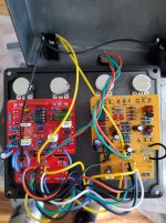
Alright so I have someone who wants a RAT/Ds1 in parallel. I got everything connected and it is passing signal but it almost seems as If the Rat doesn't have any gain at all and just the volume control works. The DS1 works absolutely fine and actually really like the sound of it. I used 2 Aion effects kits to make it an easier build with what the customer wanted for mods.

Any suggestions?

It got late and I gave up for the night.
 
How did you mix the outputs? Hopefully not by just tying them together.
This was my first shot running parallel and so far I have had almost no issues and built about 60 pedals. If I remember correctly after a night's sleep I think I ran everything in parallelfrom the boards to the foot switch. I'm thinking I know where I screwed up. Won't have time til this evening to troubleshoot. Will try and get a pic up before I leave for work.

I am almost positive my issue is coming from how I am wiring the output. It's all in parallel to a single footswitch. This was purely a let's see if this works trial run knowing it more than likely wasn't going to work right out of the gate. I am going to run both outputs to a b100k pot tonight and test from there. He wants them 50/50 anyways so I could just set it on a trimmer internally?
 
Last edited:
Without looking Aion's schematic.... The DS-1 output is buffered so it is swamping the output from the Rat.

You'll need some form of mixer at the output. It can be as simple as a pair of resistors.
Where exactly on those boards would I want to put the resistor? At the output before the footswitch I would have to assume?
 
I'm not an EE and couldn't even play one on TV, but I'd try adding a 1k 47k resistor in series between each board out and their connection to the switch... such that they're going to be bypassed when they're supposed to be. I'd try them out with alligator clips or jumping them to a breadboard before soldering in case you need to play with values... or it just doesn't work.

If there's no improvement with 1k 47k resistors, try some higher values. If those don't work, come back and wait for someone who actually knows what they're talking about.
 
Last edited:
Ok
Without looking Aion's schematic.... The DS-1 output is buffered so it is swamping the output from the Rat.

You'll need some form of mixer at the output. It can be as simple as a pair of resistors.
My first mistake was most likely running the switching in parallel as well?

I already desoldered the outputs from both pcb to the output jack
 

Attachments

  • 1782857895468817042607436460319.jpg
    1782857895468817042607436460319.jpg
    552.3 KB · Views: 11
I'm not an EE and couldn't even play one on TV, but I'd try adding a 1k resistor in series between each board out and their connection to the switch... such that they're going to be bypassed when they're supposed to be. I'd try them out with alligator clips or jumping them to a breadboard before soldering in case you need to play with values... or it just doesn't work.

If there's no improvement with 1k resistors, try some higher values. If those don't work, come back and wait for someone who actually knows what they're talking about.
Thanks for somewhere to start! I also think I have something wrong on the single footswitch that may be causing problems. This is my first parallel unit. Only build that I gave up on was the PPCB Ceasar. I couldn't ever get it to work and haven't had time to go back to it. I have build about 50 so far and I clearly need some more research and knowledge for this.
 
Thanks for somewhere to start! I also think I have something wrong on the single footswitch that may be causing problems.
If it works as expected in bypass, and you're hearing a processed Rat sound, however attenuated, I'd let the switch be for now and assume it's a mixing issue... especially since Robert indicated it's a problem.

You definitely have more wires than you need, but they might be functional as wired. It's hurting my brain to think about, so I'd like to put that off.

One thing you can check is disconnecting the SD-1's board-out wire and see if the Rat side then functions as expected. If so, that's another indicator that it's a mixing problem.

If it turns out to be something more than a mixing thing, I'll show you how I'd have gone about wiring that up. For future reference, Aion's "legacy" boards would have been a better option there since they have polarity protection and all powering filtering on the mainboard... instead of moving bits onto a daughterboard. Of course, you have to source your own parts for those, so there's always a trade-off. I feel like I have to mention that PedalPCB also puts them all on the mainboards.
Yeah i dont buy kits I source all my own parts. I just didn't think until after I ordered them that I shiukd have got the Legacy ones but figured I would try these before starting over. I unfortunately was in a motorcycle accident 2 weeks ago and am slowly on the mend and can only handle sitting and soldering for shorter periods of time right now. Had another project I needed to finished tonight. Will report back tomorrow with more issues.

Disconnecting the DS1 was going to be my first move when I start tomorrow
 
I think i fried a resistor too on the rat board. Everyone over on the DIY page on Facebook is saying the only way it's going to work is with an input buffer and am active mixer

Maybe. I don't know. I'm just telling you how I'd think about the problem. It would be cheap and easy to try the resistors first, without soldering them in.

That said, I could see where differences in input impedance might make a difference too.

It takes a pretty dedicated and sustained effort to fry a decent metal-film resistor, but it is possible. If you're over 50 pedals in at this point, I doubt very seriously that you fried a resistor.

Also, in case you're not aware, the Robert who responded to you above is the proprietor and mind behind PedalPCB. Getting his advice on the matter is as close to gospel as you're likely to get. If he says you need a mixer on the output, you do. That doesn't mean it's the only issue, but I'd sort that out first.

While I'm thinking of it, these tiny buffers have "magically" corrected some issues for me on multiple occasions. If you're not comfortable soldering SMD transistors, there is another version for through-holes.
 
Everyone over on the DIY page on Facebook is saying the only way it's going to work is with an input buffer and am active mixer

You shouldn't need an input buffer.... it wouldn't hurt, but it really should work without one.

An active mixer would certainly be ideal, but again, you should be able to passively mix the outputs.

The two yellow wires in your image (the ones between the footswitches) should be resistors, the value might take some experimentation.... start with 10K.


My first reaction was "Heck no, there's no way that 3PDT is going to work wired up like that!" but the more I think about it, aside from the LEDs it actually might work. And since it appears you're only using one LED, even that might not be an issue.

It's early though, so I might be overlooking something. (I've never seen anyone parallel two 3PDTs like that)

For now, replace those yellow wires with resistors and see what you get.
 
Maybe. I don't know. I'm just telling you how I'd think about the problem. It would be cheap and easy to try the resistors first, without soldering them in.

That said, I could see where differences in input impedance might make a difference too.

It takes a pretty dedicated and sustained effort to fry a decent metal-film resistor, but it is possible. If you're over 50 pedals in at this point, I doubt very seriously that you fried a resistor.

Also, in case you're not aware, the Robert who responded to you above is the proprietor and mind behind PedalPCB. Getting his advice on the matter is as close to gospel as you're likely to get. If he says you need a mixer on the output, you do. That doesn't mean it's the only issue, but I'd sort that out first.

While I'm thinking of it, these tiny buffers have "magically" corrected some issues for me on multiple occasions. If you're not comfortable soldering SMD transistors, there is another version for through-holes.
I definitely fried it lol.
 

Attachments

  • Screenshot_20260701-090333_Gallery.jpg
    Screenshot_20260701-090333_Gallery.jpg
    183 KB · Views: 2
You shouldn't need an input buffer.... it wouldn't hurt, but it really should work without one.

An active mixer would certainly be ideal, but again, you should be able to passively mix the outputs.

The two yellow wires in your image (the ones between the footswitches) should be resistors, the value might take some experimentation.... start with 10K.


My first reaction was "Heck no, there's no way that 3PDT is going to work wired up like that!" but the more I think about it, aside from the LEDs it actually might work. And since it appears you're only using one LED, even that might not be an issue.

It's early though, so I might be overlooking something. (I've never seen anyone parallel two 3PDTs like that)

For now, replace those yellow wires with resistors and see what you get.
Thank you for the help. I am going to try this tonight.

I did notice I fried a resistor as well? Indication of another issue?
 

Attachments

  • Screenshot_20260701-090333_Gallery.jpg
    Screenshot_20260701-090333_Gallery.jpg
    183 KB · Views: 2
I definitely fried it lol.

That looks bad, but if the mainboard is getting power, it's still doing something.

If you have a multimeter, use the continuity mode to see if it's shorted. If not, check the voltage on both sides of it. If one is just a little lower than the other, it's probably fine. I'd also check the resistance of it, but being that it's in-circuit, you'd have to take that reading with a grain of salt. To get an accurate reading, you'd have to remove it, and at that point, you might as well replace it.
Oh it's getting pulled as soon as I get home and replaced. After looking at my footswitch wiring I truly don't know what I was thinking. I have been on a bunch of pain meds and I think lesson learned is don't pain med and solder
 
Back
Top