Effects in parallel.

jlees1264

Member
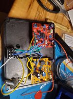
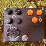
Alright so I have someone who wants a RAT/Ds1 in parallel. I got everything connected and it is passing signal but it almost seems as If the Rat doesn't have any gain at all and just the volume control works. The DS1 works absolutely fine and actually really like the sound of it. I used 2 Aion effects kits to make it an easier build with what the customer wanted for mods.

Any suggestions?

It got late and I gave up for the night.
 
If it works as expected in bypass, and you're hearing a processed Rat sound, however attenuated, I'd let the switch be for now and assume it's a mixing issue... especially since Robert indicated it's a problem.

You definitely have more wires than you need, but they might be functional as wired. It's hurting my brain to think about, so I'd like to put that off.

One thing you can check is disconnecting the SD-1's board-out wire and see if the Rat side then functions as expected. If so, that's another indicator that it's a mixing problem.

If it turns out to be something more than a mixing thing, I'll show you how I'd have gone about wiring that up. For future reference, Aion's "legacy" boards would have been a better option there since they have polarity protection and all powering filtering on the mainboard... instead of moving bits onto a daughterboard. Of course, you have to source your own parts for those, so there's always a trade-off. I feel like I have to mention that PedalPCB also puts them all on the mainboards.
Legacy boards ordered for both to make this easier
 
Without looking Aion's schematic.... The DS-1 output is buffered so it is swamping the output from the Rat.

You'll need some form of mixer at the output. It can be as simple as a pair of resistors.
Other than the bypass half does this look like this is all set for parallel? I think i got it this time compared to my total embarrassment last time 😄

Red leads would just be wired parallel from the power jack.

Green = In
Blue = Ground
Yellow = Out
Black = Switch
Red = 9V
 

Attachments

  • 20260714_195511.jpg
    20260714_195511.jpg
    492.9 KB · Views: 5
That looks bad, but if the mainboard is getting power, it's still doing something.

If you have a multimeter, use the continuity mode to see if it's shorted. If not, check the voltage on both sides of it. If one is just a little lower than the other, it's probably fine. I'd also check the resistance of it, but being that it's in-circuit, you'd have to take that reading with a grain of salt. To get an accurate reading, you'd have to remove it, and at that point, you might as well replace it.
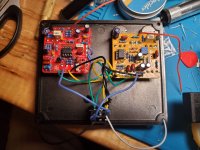
Other than the bypass half does this look like this is all set for parallel? I think i got it this time compared to my total embarrassment last time 😄

Red leads would just be wired parallel from the power jack.

Green = In
Blue = Ground
Yellow = Out
Black = Switch
Red = 9V
 

Attachments

  • 20260714_194452.jpg
    20260714_194452.jpg
    438.4 KB · Views: 8
Back
Top