
The Grand Wazoo
Member
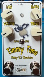
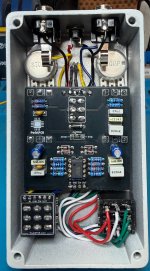
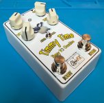
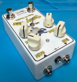
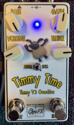
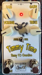
Greetings. I completed a Tommy III build. I made some modifications to the stock build. I added a second footswitch that is taking the place of the DPDT (on-on) toggle. I used the Angry Andy coordinates to place the switches and man is that tight. You really need to drill accurately to get those right. This way you can kick in the boost (gain range) while playing.
To go with the second footswitch, I used a dual color LED. When you kick the pedal on, it will show blue. When you kick on the boost, it shows red. Kinda like the Morning Glory V4.
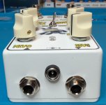
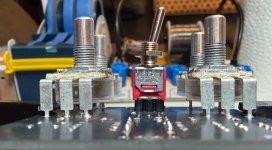
Another thing that i did was move the Diode switch outside. I just estimated the location by trying to scale an image of the PCB and putting it in my design doc. That worked out fairly well. I did this with a sub-mini PC mount toggle switch. Since the switch is short, I squeezed the pins just a tiny bit with a pair of mini-long-nose vise grips that I have. This allowed me to socket the switch in a SIP socket. This made the height very close to the pots (see image).
I have to say that I really thought that there would be more gain on tap. Based on demos I've seen of the Timmy V3, I don't think I'm getting the normal amount of gain in the normal channel. The boost (gain range) switch makes a huge jump. It would be nice if those two were a bit closer in gain. I like the more mid-forward quality of the boost for lead style playing. But if I have the gain set so that I get enough in the normal channel, it is just too big a jump to switch live. This is how I use my Morning Glory V4. FYI, my Tommy III as is, stacks very nicely with a Morning Glory V4.
If anyone has some insights on the gain issue, I'd love to hear them.
Here are some pics.
To go with the second footswitch, I used a dual color LED. When you kick the pedal on, it will show blue. When you kick on the boost, it shows red. Kinda like the Morning Glory V4.
Another thing that i did was move the Diode switch outside. I just estimated the location by trying to scale an image of the PCB and putting it in my design doc. That worked out fairly well. I did this with a sub-mini PC mount toggle switch. Since the switch is short, I squeezed the pins just a tiny bit with a pair of mini-long-nose vise grips that I have. This allowed me to socket the switch in a SIP socket. This made the height very close to the pots (see image).
I have to say that I really thought that there would be more gain on tap. Based on demos I've seen of the Timmy V3, I don't think I'm getting the normal amount of gain in the normal channel. The boost (gain range) switch makes a huge jump. It would be nice if those two were a bit closer in gain. I like the more mid-forward quality of the boost for lead style playing. But if I have the gain set so that I get enough in the normal channel, it is just too big a jump to switch live. This is how I use my Morning Glory V4. FYI, my Tommy III as is, stacks very nicely with a Morning Glory V4.
If anyone has some insights on the gain issue, I'd love to hear them.
Here are some pics.

 Perhaps I should put that test box I created to use!