Tommy III

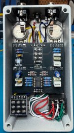
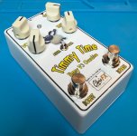
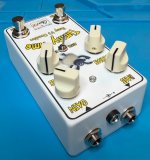
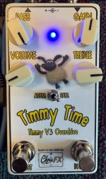
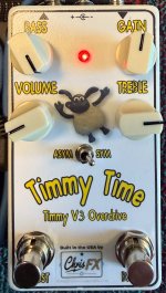
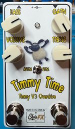
Greetings. I completed a Tommy III build. I made some modifications to the stock build. I added a second footswitch that is taking the place of the DPDT (on-on) toggle. I used the Angry Andy coordinates to place the switches and man is that tight. You really need to drill accurately to get those right. This way you can kick in the boost (gain range) while playing.

To go with the second footswitch, I used a dual color LED. When you kick the pedal on, it will show blue. When you kick on the boost, it shows red. Kinda like the Morning Glory V4.

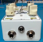
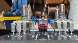
Another thing that i did was move the Diode switch outside. I just estimated the location by trying to scale an image of the PCB and putting it in my design doc. That worked out fairly well. I did this with a sub-mini PC mount toggle switch. Since the switch is short, I squeezed the pins just a tiny bit with a pair of mini-long-nose vise grips that I have. This allowed me to socket the switch in a SIP socket. This made the height very close to the pots (see image).

I have to say that I really thought that there would be more gain on tap. Based on demos I've seen of the Timmy V3, I don't think I'm getting the normal amount of gain in the normal channel. The boost (gain range) switch makes a huge jump. It would be nice if those two were a bit closer in gain. I like the more mid-forward quality of the boost for lead style playing. But if I have the gain set so that I get enough in the normal channel, it is just too big a jump to switch live. This is how I use my Morning Glory V4. FYI, my Tommy III as is, stacks very nicely with a Morning Glory V4.

If anyone has some insights on the gain issue, I'd love to hear them.

Here are some pics.
 

Attachments

  • IMG_0327.jpeg
    IMG_0327.jpeg
    299.2 KB · Views: 49
  • IMG_0328.jpeg
    IMG_0328.jpeg
    425.2 KB · Views: 48
  • IMG_0329.jpeg
    IMG_0329.jpeg
    364.3 KB · Views: 47
  • IMG_0330.jpeg
    IMG_0330.jpeg
    349.5 KB · Views: 35
  • IMG_0331.jpeg
    IMG_0331.jpeg
    280.4 KB · Views: 30
  • IMG_0332.jpeg
    IMG_0332.jpeg
    345 KB · Views: 29
  • IMG_0333.jpeg
    IMG_0333.jpeg
    345.5 KB · Views: 37
  • IMG_0316.jpeg
    IMG_0316.jpeg
    292.5 KB · Views: 42
I was just eyeing your values and cannot see an issue, Is that a 1m under the op-amp? Also where is the op-amp from?

I imagine others may be more helpful with suggestions but maybe a cap issue or a potentiometer? I do remember that they have an noticable jolt when switched. So different volumes, maybe yours in normal? Post a vid

I have built four of these and they have headroom for days.
 
I was just eyeing your values and cannot see an issue, Is that a 1m under the op-amp? Also where is the op-amp from?

I imagine others may be more helpful with suggestions but maybe a cap issue or a potentiometer? I do remember that they have an noticable jolt when switched. So different volumes, maybe yours in normal? Post a vid

I have built four of these and they have headroom for days.
I really appreciate the feedback. I will post a video as soon as I can, The first thing I did was check values against the build doc. But I haven’t re-checked the pots because I didn’t want to disassemble the pedal again. There’s a lot of wire from relocating the DPDT switch and the dual color LED 😳 Perhaps I should put that test box I created to use!
The resistor under the op-amp is a 1M. The op-amp is from Stompbox Parts.
 
Last edited:
@OD is Glorious, it's time to send out the Doofus Patrol. When I opened the pedal back up today, I found that I had installed the pots backward. Most probably because I mounted everything to the outside of the enclosure to make sure everything fit. But I installed the pots as if the board were the opposite way around (even though the values are all printed on the board and were FACING ME!). Bass had an A500K, Gain had a C50K, Volume had a C50K and Treble had an A25K.

It sounds much better now. The boost is not as drastic in gain.

I would like to tone down some of the harsh highs that the boost introduces. I may play with the value of C9 which gets switched into the circuit when the boost is engaged.

Thanks chiming in and trying to help! Sadly, you couldn't fix the problem, which was me.
 
@OD is Glorious, it's time to send out the Doofus Patrol. When I opened the pedal back up today, I found that I had installed the pots backward. Most probably because I mounted everything to the outside of the enclosure to make sure everything fit. But I installed the pots as if the board were the opposite way around (even though the values are all printed on the board and were FACING ME!). Bass had an A500K, Gain had a C50K, Volume had a C50K and Treble had an A25K.

It sounds much better now. The boost is not as drastic in gain.

I would like to tone down some of the harsh highs that the boost introduces. I may play with the value of C9 which gets switched into the circuit when the boost is engaged.

Thanks chiming in and trying to help! Sadly, you couldn't fix the problem, which was me.
Glad you figured it out. The fun of desoldering. This is one of my favorite circuits.
 
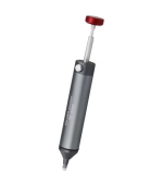
I pronbably would struggle without my solder sucker.
View attachment 121456
I have the SS-03 version. I really like the silicone tip.

But getting multi-pin components out works really well with the wire method. Pots for example (I just had to remove 4 of them) just drop out of the board. Then I use solder wick to clean up the pads. I put some flux paste on the solder wick and that just cleans them up like new.
 
@OD is Glorious...

It sounds much better now. The boost is not as drastic in gain.

I would like to tone down some of the harsh highs that the boost introduces. I may play with the value of C9 which gets switched into the circuit when the boost is engaged.
...

Great you got your pedal sorted with a helpful nudge from ODisG. (y)


1) Gain/Volume Jump...
One of the things that I like to do is add a "2knobJob" to this sort of boost — basically a pot-swapper added to the boost switch.

The second pot can be a trimmer mounted internally if you don't want/have-space-for an extra control on the face of the pedal.

Usually I'll make the boost a stomper, for which a 4PDT is needed. Two poles are for swapping the BOOST pot (a second gain control or second volume pot), the 3rd pole for LED indication the boost is active and the last pole for switching out the resistor or whatever. However ! ...

For this circuit the boost isn't a SPDT, so I'd have to sacrifice the LED-indicator, which is fine if it were still a toggle, not so great for the footswitch. However ! ...

If you were to use the 4th pole of the 4PDT stomper to swap between R4 3k3 and another pot wired as Rheostat, you'd be able to...

retain the first two poles for the stock BOOST switchery, 3rd pole for LED indication and 4th pole as above, to swap between the stock R4 and the extra pot.


2) Harsh highs introduced by the boost...
Check out Mark Hammer's SWTC (Stupidly Wonderful Tone Control); you could add it between the main circuit and the volume pot. Jack Orman has a very good version of Hammer's SWTC, and he explains it better than I ever could:

 
Great you got your pedal sorted with a helpful nudge from ODisG. (y)


1) Gain/Volume Jump...
One of the things that I like to do is add a "2knobJob" to this sort of boost — basically a pot-swapper added to the boost switch.

The second pot can be a trimmer mounted internally if you don't want/have-space-for an extra control on the face of the pedal.

Usually I'll make the boost a stomper, for which a 4PDT is needed. Two poles are for swapping the BOOST pot (a second gain control or second volume pot), the 3rd pole for LED indication the boost is active and the last pole for switching out the resistor or whatever. However ! ...

For this circuit the boost isn't a SPDT, so I'd have to sacrifice the LED-indicator, which is fine if it were still a toggle, not so great for the footswitch. However ! ...

If you were to use the 4th pole of the 4PDT stomper to swap between R4 3k3 and another pot wired as Rheostat, you'd be able to...

retain the first two poles for the stock BOOST switchery, 3rd pole for LED indication and 4th pole as above, to swap between the stock R4 and the extra pot.


2) Harsh highs introduced by the boost...
Check out Mark Hammer's SWTC (Stupidly Wonderful Tone Control); you could add it between the main circuit and the volume pot. Jack Orman has a very good version of Hammer's SWTC, and he explains it better than I ever could:

I love these suggestions! When I reversed the pots, the volume jump wasn’t as pronounced.

For the harsh highs, I pulled C9, installed a socket and replaced it with 200pF (didn’t have a 220pF so I did 2 x 100 in parallel). I haven’t fired it up yet. I’ll report back when I have.
 
Last edited:
Yeah, I saw that you'd fixed the volume jump already, but still wanted to share the idea of the 2knobjob.

Forgot to mention — GuitarPCB offers the 2knobjob PCB, but it's easy-peasy and less expensive to wire it yourself.
 
Greetings, thanks to all for their helpful suggestions. @Feral Feline, I thought about the AMZ Stupidly Wonderful Tone Control. But it really wants to go at the end of the path just before the volume pot and that isn't where I need it. The normal mode sounds very good to me.

What I wound up doing was changing out R12, which is 360R. When switched in, it's in parallel with R3 @ 3.3K giving you about 325 ohms. I socketed R12 (because I didn't have any trim pots on hand) and began experimenting. I wound up putting two 470R resistors in series giving me 940 ohms and in parallel with R3 giving me about 732 ohms. This decreased the gain and also helped to tame the rough highs that were there. I need to play it a bit more. It was a toss up between the 940 ohms and 1K ohms.

Whichever I decide on, the boost mode is much much better now. It's not so far away from normal mode that I wouldn't kick it in while playing, which was the point of putting it on a footswitch.

I'm most likely going to order a trim pot and a "Trimmit!" board from PedalPCB the next time I order so I can dial it in precisely.

If I still find the highs objectionable, I may play with the values of C9. That looks like it gives a bass boost which I think affects how the highs are amplified.

And other good news, I got to put the test box I built to use since I had to desolder the power leads. That was handy.
 
Back
Top