moonshot tremolo noise

dre

New member
hey hope someone can help.....
I had this same problem with the trembling loon (which I ultimately destroyed by replacing components) and I dont want to blindly start ripping this apart.
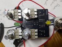
Theres a buglight static noise. The gain is pretty high unlike the posts Ive read on here...I have to keep the gain almost all the way down. It seems to get worse the longer the pedal is on. I was going to mess with R2 or R3 but the fact that its the exact same problem I had with the loon is strange. Im not experienced I cannot read schematics well....I actually bought vactrols thinking I couldnt make one right and that was the problem. Hopefully the video works. I checked the power readings on the TL072 that seems ok. Ive successfully made pedals from pedalpcb but the tremolo is killing me...thanks!
PXL_20260806_220752791.jpg
 

Attachments

I kinda hate it when threads arent resolved so Im posting a follow up. Behold my best effort to not damage the board. I think the pads are in place? but I had a hell of a time. So now with the socketed tl072 I get no sound at all. I replaced the vactrol...I burned the old one. The wires are melted a bit on the 3pdt but I doubt that would cause no sound at all. Also...I had a working Clandestine preamp that I couldnt bias correctly so I sucessfully removed and installed a socket for the Jfet (actually didnt damage that one) and now with a different Jfet I can get a good bias but again no sound on that one either. Im stumped. Im all ears if there is something glaringly wrong that Im missing but it appears the resolution is failure LOL
Screenshot_20260815-124226.png
 
I suggest getting at least one soldering through hole practice kit and using it to practice soldering and unsoldering components. They can typically be found on places like Amazon, ebay, AliExpress etc for about $10-15, much better than damaging good pedal b oards.
 
  • Like
Reactions: dre
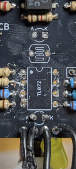
cool worth a try. pin 5 looks bad to me also. so each pin should be going to the resistor next to it? Schematics are a weak point for me
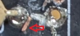
lifted/broken trace from pin 2 to resistor on left. should be easy to add a wire to connect it back
that was it dude!!!!! thanks so much! OK so from now on Im socketing all my ICs and tranistors. And yes I definitely need more practice but thanks to everyone on this thread!
 
Glad you got it working. :)
I was able to see the lifted trace on pin 2 and where it went in your photo. Guess I should've just pointed it out like this, sorry; Untitled.jpg

so each pin should be going to the resistor next to it? Schematics are a weak point for me
Not necessarily. In this case it's pins 1, 2, 3, and 5 go to the resistor next to them (on the top of the board) for that IC. That's going off the render of the board in the build document, not the schematic.

Advice for the future would be to take a picture of the bottom (and top) of the board before soldering anything, with light reflecting so you can see all the traces, and hang on to it. Helps if you need it later and can be useful with or without a schematic. Build docs usually have a render of the top of the board but not the bottom. And I always clean with iso after desoldering, but in this case that could have broken off the trace completely and made things harder to spot. You took the right photo at the right time in this case. (y)
 
  • Like
Reactions: dre
Back
Top