Warp South - Custom Greer Lightspeed/Southland

MattG

Well-known member
Build Rating
5.00 star(s)
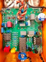
I made a PCB that supports both the Greer Lightspeed (PPCB Mach 1) or Southland (PPCB Southern Belle). The Southland is a superset of the Lightspeed: same circuit with only a couple extra hard-clipping diodes, and a few component value changes. Thus far I've only built the Lightspeed.

I built a Mach 1 about three years ago. For whatever reason, I never spent much time with it, and sold it in a decluttering frenzy. So I created this PCB partially to revisit this circuit, but also as an excuse to continue validating my MCU bypass firmware on different microcontrollers. This build uses the PIC12F675, which is an MCU I originally didn't plan to support, but found I have a number of them in my inventory.

I don't think I can add much to the discussion on the circuit itself; a lot has been said about it. It certainly seems to have a fairly neutral i.e. "transparent" EQ. It's definitely on the light end of the dirt spectrum (pun intended). It could very well be confirmation bias, but I think I get the amp-like feel that is often attributed to this circuit. For my tastes, it might be just a tad too bass-heavy, but I may come around to that. I don't think it accentuates bass at all, but it's kind of anti-tubescreamer in that it doesn't seem to cut any bass. And I think this is the right way to go for a light overdrive. But when it comes to pushing another drive (or presumably already overdriven amp), it can get a little muddy, at least for chord work. For leads I think it would actually work really well to thicken the sound. Those are just initial thoughts having done little more than the initial "does it work" play-through.

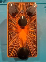
The build itself was delightfully unremarkable. I made one minor mistake in the schematic that is trivially remedied (a bogus pulldown resistor). Enclosure is Tayda "Matte Orange", and the front face is a Sunnyscopa waterslide. I currently have expensive OPA2134 opamps in there. After I've played with this a while, I might replace those with good ol' (cheap) TL072 to see if I can perceive any difference.

I have a few extra boards, shoot me a DM if you want me to drop one in the mail for you.
 

Attachments

  • IMG_3433.jpg
    IMG_3433.jpg
    355.9 KB · Views: 49
  • IMG_3429.jpg
    IMG_3429.jpg
    257.4 KB · Views: 47
  • IMG_3431.jpg
    IMG_3431.jpg
    375.9 KB · Views: 47
I've been dipping my toes in relay bypass as well. I think I'm going to try a side jack 1590b as my first foray. What kind of switch is that?

Do you mean the footswitch or the electrical switching IC?

The footswitch is one of these 16mm Mushroom Head Jog Button Switch from AliExpress. Credit to @jubal81 for turning me on to those. They appear to be clones of these Apiele Mushroom Head Switches. (Best-case, they are the actual OEM for the Apiele-branded ones.)

The electrical switching IC is a CD4053. See RG Keen's Bypassing and Switching with the CD4053 CMOS Analog MUX for an overview of analog circuit switching with the CD4053. I used to use that scheme exactly; though with the microcontroller and @jubal81's ideas, it's now more sophisticated, and involves a brief mute to avoid pops/clicks during switching.

If you want to use a microcontroller to manage a mechanical relay, my firmware supports that too.
 
I made a PCB that supports both the Greer Lightspeed (PPCB Mach 1) or Southland (PPCB Southern Belle). The Southland is a superset of the Lightspeed: same circuit with only a couple extra hard-clipping diodes, and a few component value changes. Thus far I've only built the Lightspeed.

I built a Mach 1 about three years ago. For whatever reason, I never spent much time with it, and sold it in a decluttering frenzy. So I created this PCB partially to revisit this circuit, but also as an excuse to continue validating my MCU bypass firmware on different microcontrollers. This build uses the PIC12F675, which is an MCU I originally didn't plan to support, but found I have a number of them in my inventory.

I don't think I can add much to the discussion on the circuit itself; a lot has been said about it. It certainly seems to have a fairly neutral i.e. "transparent" EQ. It's definitely on the light end of the dirt spectrum (pun intended). It could very well be confirmation bias, but I think I get the amp-like feel that is often attributed to this circuit. For my tastes, it might be just a tad too bass-heavy, but I may come around to that. I don't think it accentuates bass at all, but it's kind of anti-tubescreamer in that it doesn't seem to cut any bass. And I think this is the right way to go for a light overdrive. But when it comes to pushing another drive (or presumably already overdriven amp), it can get a little muddy, at least for chord work. For leads I think it would actually work really well to thicken the sound. Those are just initial thoughts having done little more than the initial "does it work" play-through.

The build itself was delightfully unremarkable. I made one minor mistake in the schematic that is trivially remedied (a bogus pulldown resistor). Enclosure is Tayda "Matte Orange", and the front face is a Sunnyscopa waterslide. I currently have expensive OPA2134 opamps in there. After I've played with this a while, I might replace those with good ol' (cheap) TL072 to see if I can perceive any difference.

I have a few extra boards, shoot me a DM if you want me to drop one in the mail for you.

Nice build and I love the graphic.
 
Do you mean the footswitch or the electrical switching IC?

The footswitch is one of these 16mm Mushroom Head Jog Button Switch from AliExpress. Credit to @jubal81 for turning me on to those. They appear to be clones of these Apiele Mushroom Head Switches. (Best-case, they are the actual OEM for the Apiele-branded ones.)

The electrical switching IC is a CD4053. See RG Keen's Bypassing and Switching with the CD4053 CMOS Analog MUX for an overview of analog circuit switching with the CD4053. I used to use that scheme exactly; though with the microcontroller and @jubal81's ideas, it's now more sophisticated, and involves a brief mute to avoid pops/clicks during switching.

If you want to use a microcontroller to manage a mechanical relay, my firmware supports that too.
I mean the footswitch. I see a lot of people using barefoot buttons on their foot switches and this seems to provide a shortcut to that.

I've seen hex bypasses around, and they aren't that expensive. Are they more reliable than a relay/555 timer? Is there an SMD version?
 
I mean the footswitch. I see a lot of people using barefoot buttons on their foot switches and this seems to provide a shortcut to that.

These "mushroom head" footswitches are awesome. At least the Apiele-branded ones have deliciously overkill specs for pedals. And as you said, they natively have the built-in wide-surface topper. Besides the convenience, I'd argue these switches are actually better than a traditional switch with topper: In my mind, small shaft plus the larger surface area of the topper makes it easier to torque the switch in ways for which it may not have been designed. IOW, in theory, that could lead to premature failure. The actual actuation shaft of the mushroom head switch (you're welcome for the innuendo layup!) is almost as wide as the button itself, which should make for far less awkward torquing opportunities. Plus: screw terminals! In the event a replacement is necessary, it's a five-minute in-the-field job. They're even slightly cheaper than the more common momentary SPST switches.

I've seen hex bypasses around, and they aren't that expensive. Are they more reliable than a relay/555 timer? Is there an SMD version?

On the topic of bypass, getting away from 3PDT switches, note there are really three distinct functions:
  1. The "user interface", i.e. the footswitch itself that the user presses
  2. The actual circuit-switching mechanism: this is a mechanical relay or some kind of solid-state switch
  3. The "brains" which ties together the above two functions, as well as manages state, and lights or dims the status LED

The mechanical 3PDT footswitch combines all three into a single device.

Note the CD4053 isn't a "hex" device; it is an electrical analog switch. It provides essentially the same functionality as a mechanical relay. You may be thinking of the CD40106 or 74HC14, which are both "hex inverters". I have used hex inverters in the past as the "brains" part of switching schemes, for both electrical bypass (CD4053) and mechanical relay bypass. But I have recently switched back to using microcontrollers for the "brains".

In 555-based schemes, the timer acts as the "brains". I haven't seen it done, but I don't see any reason why a 555 timer couldn't be used with a solid state relay.

I personally don't like 555-based schemes because the 555 timer draws a lot of current. I don't even use batteries, I'm just neurotic like that - I can't abide my bypass sub-circuit using more current than the effect itself! There is a CMOS-based 555 variant (I forget the part number) which has lower current draw, but it's still too high (IMO) for this role.

In terms of reliability: mechanical 3PDT footswitches are kinda lousy. Though I don't have personal experience, I get the impression that when these were first introduced, the reliability was pretty awful. I suspect modern production ones are reasonably decent. But still, compared to other options discussed here, they are the worst.

Based on what I've read, modern sub-miniature mechanical relays (like the Panasonic TQ2 series) are pretty impressive devices. I think they are rated for 1mm mechanical cycles. The electrical cycle rating is much lower, like 100k but that assumes pretty adverse switching conditions (like high voltage/high current DC). In effect pedals, we're switching low voltage AC, so we can reasonably assume that the number of electrical cycles is roughly the same as mechanical cycles. To put it another way: if I toggle my effect (more innuendo) 100x/day, every single day, I can still expect the relay to last nearly 30 years. Even a professional touring/studio musician can expect a modern mechanical relay to last a lifetime.

In theory, mechanical relays are more sensitive to environmental factors, particularly impact. If you drop a pedal with a relay, it could possibly set (or reset). Depending on how the "brains" are implemented, it could potentially be rendered out-of-sync with the status LED and actual bypass/engage state; or it could be a non-issue if the "brains" have some kind of always-set-to-a-known-state at power-on scheme. More realistically, the kinds of impact forces that could actually destroy a relay are higher than what would kill other components or even solder joints first.

Electrical switching schemes, such as the CD4053 (like I'm using here) should quite literally last forever. There are no moving parts, only moving electrons. And they are of course relatively immune to impact forces. The are the "best" in terms of longevity, but in practical terms, it's probably a wash compared to mechanical relays.

One potential advantage mechanical switching has over electrical switching is "true" bypass. This is for the version of "true" that means the effect circuit is totally air-gapped from the bypass signal. You can wire an electrical switch like the CD4053 to be "true" bypass in the sense that the effect circuit is completely removed from the bypassed signal - but it won't be an air-gapped removal, it will be "transistor-gapped".

However, that said, while you could technically have a non-buffered electrical bypass, you probably don't want to. Electrical switches do put a small bit of capacitance and resistance in the signal path, and this could be an issue, depending on the surrounding impedances. That's why you almost always see electrical bypass schemes used with a buffer. The buffer changes the electrical switch's parasitic capacitance/resistance from "potential problem" to "doesn't matter".

Whew, that was meant to be a short answer, but turned into an essay! I'm a self-described bypass enthusiast. :)

Also, FWIW: the CD40106 and 74HC14 hex inverters are available in both through-hole and SMD packages; though they've been around a long time, both package types are still current-production commodity parts (i.e. low-cost and readily available). The same goes for CD4053. However, if going surface-mount with CD4053, there is a pin-compatible but upgraded version, the TMUX4053.
 
Thanks for the long and girthy explanation!

I'm contemplating implementing the option for the pedal to run on a battery - at least until the player can go out and pick up a power supply. I don't want to rely on expecting every buyer to be as electronic or gear savvy as us and I want to explore trying to accommodate for that, even nowadays when power supplies are so seemingly ubiquitous. True bypass relay switching is the most appealing for this scenario.

Is there an advantage to using a microcontroller as the "brains" for a relay over a hex inverter?
 
Is there an advantage to using a microcontroller as the "brains" for a relay over a hex inverter?

There are differences, and whether those are advantages: it depends. Off the top of my head, these are the considerations that come to mind:
  • Footprint: the CD40106 and 74HC14 are 14-pin devices, whereas the MCUs I'm using are 8-pin devices. But footprint isn't the whole story, as you have to consider supporting components:
    • The CD40106 has a wide voltage range, up to 20 volts IIRC, so it can run on the effect circuit's "native" voltage (9-18v), so it saves you an LDO. Most MCUs are going to want 5 or 3.3 volts; the 74HC14 also needs <9v. Relays are available in a variety of voltages, but 9v relays are uncommon and therefore expensive. 5v relays are super common, therefore, my suggestion: use 5v for relay and the brains, regardless if it's a hex inverter or MCU.
    • Power-on state: MCU definitely wins here, as the software can ensure a consistent power-up state, or even "remember" the last-used state. I don't know how you could remember last-used state with the hex inverter. By default, the hex inverter's power-on state will be non-deterministic. You can make it deterministic, but it requires extra components; not hard, but does consume more PCB space.
    • Driving the relay: the hex inverter itself can't source/sink enough current to drive the relay coils, so you'll use it to drive transistor gates; the transistors do the current sourcing/sinking. @Chuck D. Bones did some work to show that the ATtiny13A can safely directly drive the relay coils (it has sufficient current sourcing/sinking capability and integrated protection diodes). So from this perspective, the MCU saves on supporting circuitry. (Note that I personally prefer a "belt-and-suspenders" approach, and have the MCU drive mosfet gates, i.e. the same as if I was using a hex inverter.)
    • Floating leads: this is one thing that turned me away from using hex inverters: I had at least one footswitch lead which was technically floating (i.e. not explicitly pulled up or down). Though I never had any issues with spurious state changes, it remains a theoretical possibility. Twisted footswitch leads, the aluminum enclosure, and Schmitt trigger inputs all help avoid unintended state changes. That said, with still more supporting components, it should be possible to get away from (or at least further reduce the risk of) floating leads. This issue is completely side-stepped with MCUs.
  • Cost: I just did a quick check on DigiKey: CD40106 DIP-14 is $0.77; ATtiny13A DIP-8 is $1.13. In small quantities I'd call that a wash, but note it doesn't tell the full story given the supporting circuitry discussion.
  • Robustness: I'd argue the MCU wins here, IFF the firmware is solid. I've put a lot of effort into building an extensive test and validation suite for my firmware; the core debounce/state algorithm is a pure implementation that is provably correct. Exhaustive testing and simulation backs up the hardware implementation details. With solid firmware, you can achieve robustness that I think would require still more extensive supporting components to replicate in hardware. (I'm admittedly biased here, given the amount of effort I've put into the firmware. The hex inverter approach is in all likelihood generally good enough for pedal use.)
  • Flexibility: hard win for the MCU here if you need that flexibility. For example, if you want a richer control interface, such as double-tap or press-and-hold support: that would be painful to do in hardware, but is effectively trivial in MCU software.
  • Programming/flashing: a definite win for the hex inverter, as it requires no programming. An MCU must be programmed aka "flashed", that is, have the actual firmware code written to the device itself. This requires an additional device (a programmer), and an extra step. It's a very easy/mechanical step, but I feel like it scares some people away from this approach. Additionally, if there doesn't exist free and/or open source firmware that meets your needs, you have to write the firmware yourself.
  • Fitness to application: the way you wire a hex inverter for use as bypass "brains" - which actually only uses two or three of the inverters - is a well-known trick, but it is a trick. The wiring effectively results in a "toggle flip flop". Note there are cheap, current production CMOS flip flop ICs, such as CD4013, which are arguably better suited to this task. The trade-off is that, at least with through-hole devices, there's no flip-flop IC with Schmitt trigger inputs. The CD40106 and 74HC14 inverters have Schmitt trigger inputs. Schmitt inputs are nice here because they add some noise resistance and also help with switch debounce. So, if you chose to use a CD4013, all your debounce and noise protection lives only in the RC network between the footswitch and the IC input lead. This is another reason I decided to go with the MCU: I have multiple layers ("belt-and-suspenders") of debounce and noise remediation: the RC network, Schmitt trigger inputs (at least on the ATtiny devices), and software that is purpose-built for the task.

Hope that helps! Happy to elaborate on anything if it's not clear.
 
Back
Top