Help needed to design OD1/OD2 pedal from MG100DFX Amp

Reconciledheart

New member
Good day everyone

I hope this message finds you well.

Over the last year I started getting into guitar pedal building and truly enjoy it, but have not been able to find a pedal build that has the exact sound I am looking for. I have built a Kliche, Julia Clone, Face Melter, ADHD, Thermionic Distortion and a Spatialist Reverb. All are brilliant and I cannot choose between them so all of them are on my board.

My absolute favorite overdrive/distortion is the OD channel 1/2 on a MG100DFX.

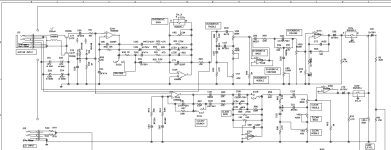
Would it in any way be possible to isolate that part of the schematic and have a design drawn up and schematic and gerber files made to include the layout with a switch to toggle between OD1/OD2, Gain, Bass, Middle, Treble, Contour and Volume controls? If it would be, what would the costs be and who would be able to provide this service? It won't be commercial, just for me and a few friends but after hearing horror stories about scammers on Fiverr it's safer for me to not go that route. I have a quality schematic that I can send of the MG100DFX as well.

Kindest Regards, John
 
Feral I am sorry, I am still limited to sending direct messages to Admin at the moment.

Thank you very much for your comment on my post with regards to possibly making a design of a MG100dfx OD1/2 pedal.

Would you be able to design a schematic of a pedal based on it and if you can, what would the costs be? Thank you😀
 
I have a PCB for a similar Marshall amp circuit somewhere.... I don't think it was the MG100 but the circuit looks close. Maybe it was a practice amp sized version of the same line? I can't recall, but it might be possible to modify it into what you're wanting.

I'll do some digging and see if I can find it. My track record ain't the best here lately though, so don't turn down any offers in the meantime. :ROFLMAO:
 
I can see the potential for this, but I'm not far enough down my own Pedal-Path to wrangle this to submission.

Someone else want a crack at it?


anyone.gif
 
I have a PCB for a similar Marshall amp circuit somewhere.... I don't think it was the MG100 but the circuit looks close. Maybe it was a practice amp sized version of the same line? I can't recall, but it might be possible to modify it into what you're wanting.

I'll do some digging and see if I can find it. My track record ain't the best here lately though, so don't turn down any offers in the meantime. :ROFLMAO:
I would truly be grateful, thank you for being willing to help:D
 
I played around with this a bit, trying to make it a unipolar supply (just +9V) which looked reasonable given the clipping diodes in the main gain stage anyway. (caveat: I have no idea what I'm doing) When I simulated it in kicad I got all kinds of trouble, tho, but I'm not sure how much of that is my limited experience in playing with the simulator. I'll see if I can breadboard something in the next week or so if I get a chance.
 
z2miller I am really sorry for my late reply I missed the notification on my mail. I am truly grateful for your time and being willing to assist me and for coming so far:D
 
@Reconciledheart I did play around with this on the breadboard a bit this weekend for funsies,
with a bipolar supply (+9/-9V). I got as far as the main gain stage, I haven't gotten through the
whole tone stack part yet. I might try it again next week with a unipolar supply + vref
to keep the parts count down but I'm heading out of town for a week so it'll be a bit.

It is clippy asf, almost a square wave coming out of the gain stage, but maybe that's how
it's supposed to sound. (metal!)

One hassle about this is that it has so many controls, any more than 6 controls and it gets harder to fit
in a 125B. (looks like it has Gain, Treble, Mid, Bass, Contour, Volume, and then the OD1/OD2 switch).
Are any of these controls like set-it-and-forget-it, like you always leave it on OD1 or OD2?
If one of the controls stayed internal, it'd be easier to lay out.

(Yeah, could do another footswitch or something for OD1/OD2, or an offset layout, as well...)
 
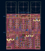
I haven't gotten this all breadboarded, but I just yolo'ed a through-hole PCB layout and will order a stack of 'em next time I order from JLCPCB, and see how it works. If it makes any reasonable noises I'll release the gerbers for people to try out.
 

Attachments

  • Screenshot 2025-11-03 at 11.42.12 PM.png
    Screenshot 2025-11-03 at 11.42.12 PM.png
    372.8 KB · Views: 17
I dunno if @Reconciledheart is still around, but I'm going through and cleaning up my old crappy schematics and repositories one by one and ran into this one again. I did a little troubleshooting with simulations and as far as I can tell, it's supposed to clip into near-square-wave-territory really easily. So anyhow, I haven't had this fabbed yet but I'm just going to release the whole thing as-is.

Notes:
* I tried to make this support either PedalPCB style (GND/9V up at the top, 4 pins for footswitch at the bottom) or my JST-PH header style. The gerbers for my footswitch breakouts are in my pedalfx repo.
* It's a conversion from a +/- 15V effect and I've tried to maintain maximum fidelity with the original. You can run this on 9V but that might change the tone a bit since the first stage is more likely to clip. If you run this with an 18V adapter it should be completely true to the original. Sure I guess I could tone down the first gain stage to try to match on 9V, or go nuts and make the board a foot long with a charge pump on there, but I didn't.
* I added a bunch of power supply filtering (not exactly in the original since it brought its own power supply that was filtered however it wanted). What's on the board is a capacitor multiplier that buys quite a bit of extra power supply ripple rejection at the cost of some extra components and a little bit more voltage drop (about 1V total including the reverse polarity diode). If you've got a clean power supply that's only 9V and want to buy some more headroom so the first stage doesn't clip, you can replace the resistor with a 47R or something, leave out Q1, and jumped Q1 pins 2 and 3 which buys you ~0.3V or something. Or you can totally raw dog it and jumper straight from the input side of the protection diode to a jumpered Q1. But really you should just run it at 18V.

Here's the whole KiCad project (CERN-OHL-P-2.0 license):

I generated the gerbers in case you can't be arsed to get KiCad working so you can order it (relatable):

Interactive build doc:

I'll probably throw this in my next JLC order and try to build it, but Idunno when that'll be. If you decide
to order/build it, let me know how it goes!
 
Actually on second thought, this can be pretty 9V-friendly by changing the first stage gain.
It drops the overall gain of the pedal by a bit but honestly since it used to be the frontend
of an amp, matching the total gain out of the effect is kind of irrelevant anyway -- you're already
going to be playing into some other amp.

I also changed the taper on the gain pot in there. Originally I kind of handwaved over figuring out
the taper of the pot since it was marked as G1M. Turns out that G1M is not only a log
pot, it's an EXTRA log pot, so B1M was an especially bad choice. I changed it to A1M
so the gain control should be a lot smoother. I've already updated the boards and gerbers.
(v0.4 is current).
 
I dunno if @Reconciledheart is still around, but I'm going through and cleaning up my old crappy schematics and repositories one by one and ran into this one again. I did a little troubleshooting with simulations and as far as I can tell, it's supposed to clip into near-square-wave-territory really easily. So anyhow, I haven't had this fabbed yet but I'm just going to release the whole thing as-is.

Notes:
* I tried to make this support either PedalPCB style (GND/9V up at the top, 4 pins for footswitch at the bottom) or my JST-PH header style. The gerbers for my footswitch breakouts are in my pedalfx repo.
* It's a conversion from a +/- 15V effect and I've tried to maintain maximum fidelity with the original. You can run this on 9V but that might change the tone a bit since the first stage is more likely to clip. If you run this with an 18V adapter it should be completely true to the original. Sure I guess I could tone down the first gain stage to try to match on 9V, or go nuts and make the board a foot long with a charge pump on there, but I didn't.
* I added a bunch of power supply filtering (not exactly in the original since it brought its own power supply that was filtered however it wanted). What's on the board is a capacitor multiplier that buys quite a bit of extra power supply ripple rejection at the cost of some extra components and a little bit more voltage drop (about 1V total including the reverse polarity diode). If you've got a clean power supply that's only 9V and want to buy some more headroom so the first stage doesn't clip, you can replace the resistor with a 47R or something, leave out Q1, and jumped Q1 pins 2 and 3 which buys you ~0.3V or something. Or you can totally raw dog it and jumper straight from the input side of the protection diode to a jumpered Q1. But really you should just run it at 18V.

Here's the whole KiCad project (CERN-OHL-P-2.0 license):

I generated the gerbers in case you can't be arsed to get KiCad working so you can order it (relatable):

Interactive build doc:

I'll probably throw this in my next JLC order and try to build it, but Idunno when that'll be. If you decide
to order/build it, let me know how it goes!
Z2Amiller, I don't know how to say thank you. Thank you for the time that you have invested in this and for making it possible for me, you will never know how much this means to me. I am placing an order with JLCPCB by latest next week and will order the pots as well from Tayda and if all goes well it should be finished by end of September factoring in the shipping times. I will definitely keep you updated:D
 
Good evening Z2AMiller😀

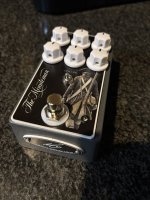
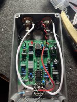
Bud I just wanted to say thank you, for the time that you invested in this and for making it possible for me. I received my boards from JLCPCB this morning and finished it up. Please excuse the mess, I was fault finding which ended up being a rookie mistake having wired the dc socket as center positive instead of center negative getting the tabs mixed up. Once that was sorted, it sounds absolutely amazing and EXACTLY like the amp.

This really is a dream come true, it’s quiet, and makes me happy.

There are at times ghost notes/overdrive underneath the distortion as it fades out, but I believe it’s my Dirty Fingers pickup as the same thing happens with a JHS Charlie Brown clone. I will verify with lower output pickups tomorrow, but as it is, it sounds amazing and I am really grateful for making this possible, I’ll also neaten the wires😀 IMG_2007.jpeg IMG_2006.jpeg
 
I received my boards from JLCPCB this morning and finished it up
Aw snap, thanks so much for the feedback! I'm super jazzed that it works and that it sounds like the original - I had nothing to compare it to other than the schematic, so I'm totally thrilled that my hack-ass translation job worked.

I like your face/bottom plates. Do you laser print those at home? The bottom plate is not only a good branding thing but also gives you a screw through the enclosure to guarantee grounding. For a lot of my designs, I use a single snap-in board with the jacks, so I've been doing my enclosure grounding with a honkin big star washer+ring washer under the footswitch. But a tiny star washer connector that goes from bottom plate screw to ground would probably be easier to deal with.

BTW the stupid polarity on the DC jacks is exactly why I ended up making a IO daughterboard/footswitch board combo, so I couldn't possibly mess it up. That's what the unpopulated JST connectors are for on this board -- though to tell the truth I've probably messed that up with the capacitor placement.... probably would have to leave the leads long and fold them 90 degrees to get the footswitch board+JST connectors to fit. Good thing I'm not trying to do anything commercially. :-)
 
Back
Top