Thermionic deluxe no sound

Satorion

New member
Hello

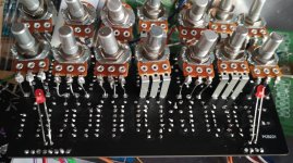
My name is Jimmy from Finland and new member here. Finished my first build but no sound. Sound goes thru the pedal when its of and when i press the left button. But goes silent when i press the button on the right, weird.. Have no clue were to start looking? Any suggestions would be appreciated. IMG_20210317_195811.jpg
 
Welcome to the forum!

If it's possible, post some additional photos including the solder side of the board as well as the connections to the switches. That will help in getting people to help diagnose what's going on.

I don't have a lot of experience debugging, but the problem you describe comes up relatively often with lots of other boards and it tends to be something fairly simple: a diode that's in backwards, bad solder joint, doing the I/O backwards, that kind of thing so be sure to double check that all of your wires are going to where they need to be.
Thanks for the reply, forgot to write that i have checked the diods and i think the capacitors are ok? Will take a photo of the solder side tomorrow.
 
I agree with @peccary . The majority of troubleshoots tend to be a simple fix. Two other items I would put on his list: do all of your ICs have power going to them? I would check with a multimeter. The other one is to check that all your pots are turned up. Don't laugh, I've done it and spent at least an hour going down my troubleshoot checklist without realizing my volume pot was turned all the way down.

We need to rule out the obvious, quick fixes as mentioned before we start checking all the individual components with multimeters and audio probes.
Thanks for the suggestions, i've put pots somewhere in the middle so that can be ruled out. Will check the ic:s after work!
 
Jimmy as everyone has said there are simple things you can check that we've all done as beginners plugging our in and out cables into the wrong in and out jacks easy to do with the pcb the wrong way up

Normally your in would be on the right flipped wrong way up it's on the left you would still get bypassed signal if you did this but no effect signal

When you say sound goes through with the left footswitch active and cuts out with the right do you mean effects sound or just bypassed sound?

The very first thing you should do is a check you get power to the pcb + and - pads then a visual check of all of your components making sure they are the correct value and polarized components are oriented the correct way

You can use resistor colour band calculators like this

https://samstechlib.com/15924820/en/

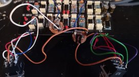
Post a picture of all of your offboard wiring to the in and out jacks, 3PDTs and DC jack so that it can be traced

All your values and orientation look correct to me, can't see R34 but still best to check everything yourself I can miss things the same as anyone else
 
Do any of the internal LEDs light up?

Do either of the front panel LEDs light up?

When you say "button on the left," do you mean when the board is out of the box with the parts facing up or when the box is fully assembled and the buttons are facing up?
 
Do any of the internal LEDs light up?

Do either of the front panel LEDs light up?

When you say "button on the left," do you mean when the board is out of the box with the parts facing up or when the box is fully assembled and the buttons are facing up?
No leds light up except, left and right led when engaging each Channel. I mean channel 1 and 2, sound goes thru the pedal when channel 1 is on and of but goes silent when channel 2 is engaged.
 
Well I guess we don't have to worrk about the pot bodies contacting the board!

Tell us about how you installed the trimpots because they don't exactly have the right footprint.

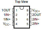
OK, now we have some better info. Look for anything that is visually different between channels. Then measure the voltage at every opamp pins 1 and 7. Compare the two channels and look for a discrepancy.
Opc:s measured:

Ic1 1,459v

Ic2a 4,59v
Ic3a 1,443v
Ic4a 1,449v

Ic2b 4,59v
Ic3b 1,468v
Ic4b 1,449v
 
Jimmy as everyone has said there are simple things you can check that we've all done as beginners plugging our in and out cables into the wrong in and out jacks easy to do with the pcb the wrong way up

Normally your in would be on the right flipped wrong way up it's on the left you would still get bypassed signal if you did this but no effect signal

When you say sound goes through with the left footswitch active and cuts out with the right do you mean effects sound or just bypassed sound?

The very first thing you should do is a check you get power to the pcb + and - pads then a visual check of all of your components making sure they are the correct value and polarized components are oriented the correct way

You can use resistor colour band calculators like this

https://samstechlib.com/15924820/en/

Post a picture of all of your offboard wiring to the in and out jacks, 3PDTs and DC jack so that it can be traced

All your values and orientation look correct to me, can't see R34 but still best to check everything yourself I can miss things the same as anyone else
Here is a picture of the wiring IMG_20210318_181733.jpg
 
Measured again..
Ic1: pin1 4,59v, pin7 1,46v

Ic2a: pin1 4,59v, pin7 4,59v
Ic3a: pin1 1,44v, pin7 1,418v
Ic4a: pin1 1,453v, pin7 1,442v

Ic2b: pin1 4,59v, pin7 4,59v
Ic3b: pin1 1,467v, pin7 1,442v
Ic4b: pin1 1,449v, pin7 1,44v
 
Measured again..
Ic1: pin1 4,59v, pin7 1,46v <---- PROBLEM

Ic2a: pin1 4,59v, pin7 4,59v
Ic3a: pin1 1,44v, pin7 1,418v
Ic4a: pin1 1,453v, pin7 1,442v

Ic2b: pin1 4,59v, pin7 4,59v
Ic3b: pin1 1,467v, pin7 1,442v
Ic4b: pin1 1,449v, pin7 1,44v

All pins should read close to 4.5V. IC1-7 is the wrong voltage and that affects IC3 & 4 (both channels). Check R35 & R36, one of them is probably the wrong value. Either that or there is a short or bad solder joint on the board. Measure the voltage on each side of R35 (one at a time, w.r.t. gnd). Then measure IC1-5.
 
Measured yet again, sorry for my fumbling..
Ic1: pin1 4,59v, pin7 1,465v
Ic2a: pin1 4,59v, pin7 4,59v
Ic3a: pin1 1,445v, pin7 1,447v
Ic4a: pin1 1,457v, pin7 1,455v

Ic2b: pin1 4,59v, pin7 4,59v
Ic3b: pin1 1,472v, pin7 1,471v
Ic4b: pin1 1,455v, pin7 1,454v
 
Back
Top