Chuck D. Bones
Circuit Wizard
I'm feeling a bit nostalgic on this one, my first PedalPCB project from August 2018. I've had a love/hate relationship with the Big Muff for many, many moons. For all it's potential, I've struggled to get one to sound the way I like. Smarter people might say "maybe you're building the wrong pedal." I was intrigued by EQD's use of Germanium transistors and LEDs in the clipping stages. Fast forward 5 1/2 years and I thought I'd revisit the design, this time on a breadboard.
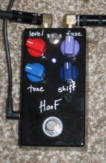
Here's my original build:
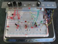
And here's the breadboard...
Knobs (L-R): LEVEL - TONE - SHIFT - FAT sw - FUZZ
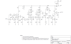
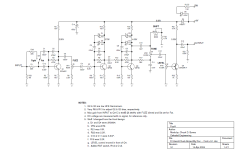
I found that the best transistors for the clipping stages (Q2 & Q3) are low-HFE Germanium. I have two MP38 installed; their HFE measures around 50-55. The leakage was low enough that I did not need to tweak the bias. DC voltages are noted on the schematic. This is a medium-gain pedal. With these transistors, the distortion is never harsh. I tried a couple of 2N1308s and it was way too nasty. I tweaked a few component values in the tone stack. The TONE and SHIFT knobs are now usable over their entire range. The biggest improvement was adding the FAT switch up front. As you know, the BMP is bottom-heavy. Probably ok with a Strat, but too muddy for my liking with Humbuckers. The FAT switch clears that right up. C1A can be tweaked to taste. Be careful about fiddling R1A. I had 10K in there and it allowed C1A to resonate with the pickup's inductance yielding a stuck-wah honk. The other thing I did, and it's completely optional, was move the LEVEL control before the last stage. Just for fun, I replaced Q4 with a JFET. In the original circuit, Q4 had enough gain to saturate on the peaks when TONE was dimed. With the LEVEL control ahead of the last stage, we can better control the signal level. We can get plenty of output at all TONE settings without saturating the last stage. As a bonus, we get a lower output impedance.
BTW, if you notice your American friends acting crabby or distracted today, it's because it's Tax Day. I used to live near LAX and for fun I would drive down to the Postal Annex around 11:30PM on 4/15 to watch people line up to mail their tax forms at the last minute. I even witnessed one poor guy filling out his forms on the sidewalk under a street lamp.
Here's my original build:

And here's the breadboard...
Knobs (L-R): LEVEL - TONE - SHIFT - FAT sw - FUZZ

I found that the best transistors for the clipping stages (Q2 & Q3) are low-HFE Germanium. I have two MP38 installed; their HFE measures around 50-55. The leakage was low enough that I did not need to tweak the bias. DC voltages are noted on the schematic. This is a medium-gain pedal. With these transistors, the distortion is never harsh. I tried a couple of 2N1308s and it was way too nasty. I tweaked a few component values in the tone stack. The TONE and SHIFT knobs are now usable over their entire range. The biggest improvement was adding the FAT switch up front. As you know, the BMP is bottom-heavy. Probably ok with a Strat, but too muddy for my liking with Humbuckers. The FAT switch clears that right up. C1A can be tweaked to taste. Be careful about fiddling R1A. I had 10K in there and it allowed C1A to resonate with the pickup's inductance yielding a stuck-wah honk. The other thing I did, and it's completely optional, was move the LEVEL control before the last stage. Just for fun, I replaced Q4 with a JFET. In the original circuit, Q4 had enough gain to saturate on the peaks when TONE was dimed. With the LEVEL control ahead of the last stage, we can better control the signal level. We can get plenty of output at all TONE settings without saturating the last stage. As a bonus, we get a lower output impedance.

BTW, if you notice your American friends acting crabby or distracted today, it's because it's Tax Day. I used to live near LAX and for fun I would drive down to the Postal Annex around 11:30PM on 4/15 to watch people line up to mail their tax forms at the last minute. I even witnessed one poor guy filling out his forms on the sidewalk under a street lamp.
Last edited:


