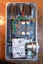
Can you modify the old board with the XLR leads?Latest version of the Volume-only Preamp adds an integrated DI. It pairs with the combo pedal posted here: https://forum.pedalpcb.com/threads/...absim-noise-gate-post-boost.21199/post-268081
View attachment 70241
View attachment 70242
You are using an out of date browser. It may not display this or other websites correctly.
You should upgrade or use an alternative browser.
You should upgrade or use an alternative browser.
TPA3118 60W Power Amp Module
- Thread starter falzhobel
- Start date
Paul.Ruby
Active member
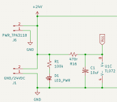
Same supply to both but I have an RC filter on the preamp boards. Here's a schematic snippet of the power supply. J1 is the power coming in from the power jack and that is sent directly over to J6 to feed the power amp. R16 and C1 are the RC filter to provide clean power to the preamp circuit. About 1V is lost across R16, which doesn't matter at all.hi friend, sorry to call you back after years have passed. im wanting to build something very similar and i really liked your approach, very simple and effective. i was wondering, did you use a regulator for the preamp power supply or did you feed it 18v same as the power amp? thanks a lot keep it rocckin lml siick riffs
Last edited:
Paul.Ruby
Active member
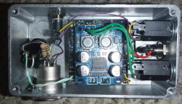
Nope. The new board has a THAT1646 chip to do the XLR driving. It's a significant circuit addition. But, there might be room to add a stand-alone balanced send using the same circuit. I've since added a ground lift switch as well. The above picture shows no ground connection to pin 1 of the XLR but had some BUZZ. Some situations need the ground and some don't. I also made a significant error in the circuit which is unsafe against phantom power. Had to add some flying bi-polar caps and 1M resistors to ground to the XLR pins.Can you modify the old board with the XLR leads?
Paul.Ruby
Active member
By the way, the reason I can combine the power amp and XLR send is that I have a cab sim ahead of this built into my all-in-one preamp, which is over here:Nope. The new board has a THAT1646 chip to do the XLR driving. It's a significant circuit addition. But, there might be room to add a stand-alone balanced send using the same circuit. I've since added a ground lift switch as well. The above picture shows no ground connection to pin 1 of the XLR but had some BUZZ. Some situations need the ground and some don't. I also made a significant error in the circuit which is unsafe against phantom power. Had to add some flying bi-polar caps and 1M resistors to ground to the XLR pins. View attachment 73800
https://forum.pedalpcb.com/threads/...absim-noise-gate-post-boost.21199/post-268081
Gotta have a cab sim ahead of any form of DI. I've found that the cab sim signal is fine for driving the power amp and real cab. Can't tell the difference with our without the cabsim ahead of the power amp, so that enabled some considerable simplification.
Paul.Ruby
Active member
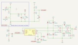
This would be the schematic to make an add-on board for DI installed in an existing Volume-Only power amp build using the old board. The signal is grabbed after the first gain stage on the TL072 and then divided down to get the right level into the 1646. But, it's probably safe to go directly from the input jack to C22 without R18 and R19. This schematic is fixed to be safe if phantom power is applied. If there is interest, I might have a PCB made since I have... Many... older power amps I could stuff this in. The GND lift is not shown here. That's wired in without needing anything on the PCB.By the way, the reason I can combine the power amp and XLR send is that I have a cab sim ahead of this built into my all-in-one preamp, which is over here:
https://forum.pedalpcb.com/threads/...absim-noise-gate-post-boost.21199/post-268081
Gotta have a cab sim ahead of any form of DI. I've found that the cab sim signal is fine for driving the power amp and real cab. Can't tell the difference with our without the cabsim ahead of the power amp, so that enabled some considerable simplification.
Paul.Ruby
Active member
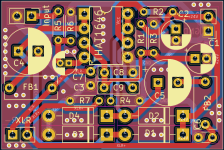
Designed a PCB for an add-on DI using this schematic... 1"x1.5" Have not ordered any as yet. The annotations don't align with the above schematic. I started from scratch to do the PCB.This would be the schematic to make an add-on board for DI installed in an existing Volume-Only power amp build using the old board. The signal is grabbed after the first gain stage on the TL072 and then divided down to get the right level into the 1646. But, it's probably safe to go directly from the input jack to C22 without R18 and R19. This schematic is fixed to be safe if phantom power is applied. If there is interest, I might have a PCB made since I have... Many... older power amps I could stuff this in. The GND lift is not shown here. That's wired in without needing anything on the PCB.
View attachment 73838
I'd be down if you make a few.Designed a PCB for an add-on DI using this schematic... 1"x1.5" Have not ordered any as yet. The annotations don't align with the above schematic. I started from scratch to do the PCB.
View attachment 73841
Paul.Ruby
Active member
Have ordered some...I'd be down if you make a few.
I will order bigger enclosures...Have ordered some...
Paul.Ruby
Active member
Paul.Ruby
Active member
Paul.Ruby
Active member
Would be cheaper for you to order direct from PCBway than for me to ship to Australia. Once I've tested them, I can share the project for others to order. I'm making 2 types: single ended power supply for this add-in board and one that takes +/-15V.I'll grab a couple of those boards too please (shipped to Australia, if you will).
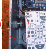
I don't understand? There is one power jack. Do you mean this? That's a push button gnd lift switch for pin 1 of the XLR.
Ah, makes perfect sense.
Either/or!Would be cheaper for you to order direct from PCBway than for me to ship to Australia.
Similar threads
- Replies
- 15
- Views
- 1K
- Replies
- 3
- Views
- 370
- Replies
- 9
- Views
- 838


