I've got a 3-channel intelligent relay bypass module and am very happy with it. Is it possible to have a configuration such as 3 switches, with maybe 4 bypass modules - giving options A, B, C, and bypass(A/B/C)= output D instead of turning off the active channel to get bypass of all 3 modules? My goal would be to have a clean "preamp pedal/channel" active whenever bypassing A/B/C, and use each A/B/C as a gain channel for a 4-channel pedalboard into a power amp.
You are using an out of date browser. It may not display this or other websites correctly.
You should upgrade or use an alternative browser.
You should upgrade or use an alternative browser.
Intelligent Relay Channel Switching Bypass Question
- Thread starter falkry05
- Start date
Feral Feline
Well-known member
Wouldn't a dual-channel looper do what you want?
Channel A has the 3-channel intelligent relay for A,B,C
Channel B has the clean preamp
You could do it with a single 3PDT, or add an extra 3PDT for master bypass of both ChA & ChB.
Channel A has the 3-channel intelligent relay for A,B,C
Channel B has the clean preamp
You could do it with a single 3PDT, or add an extra 3PDT for master bypass of both ChA & ChB.
Paul.Ruby
Active member
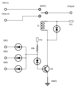
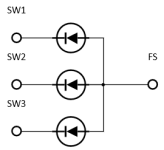
Another board is needed to do exactly what you want. This other board would detect the state of all three channels being bypassed and engage one final relay to switch in the clean channel. The SW pads on the bypass modules are perfect for this. Something like this... Each SW is isolated from each other with the diodes but any one of them being on will shut off the transistor and relay. You can still put an LED on each SW, too.

That said, have you tried having your clean channel at the end of the chain (after all the dirt channels) and leave it always on? I mention this because I really like using overdrive in front of a clean preamp, such as the fender channel of an AMT legend series pedal.
By the way... If you are able to program an attiny, you could buy a 4th intelligent bypass and reprogram it to watch the SW lines... You would combine the SW signals with diodes, just like above and then wire the combined SW line (anodes of the diodes) as the foot switch input to the 4th module. It won't work with the standard code but could be made to do so easily.
Last edited:
Any tips on what Q1 would be? Anything that can be used as a switch to trigger the relay? Programming is a bit beyond my skill level today.
I'm thinking this might be used for a "ampless" setup where a power amp only would be used. I have a 3-up intelligent relay that works great, trying to push into other options.
I'm thinking this might be used for a "ampless" setup where a power amp only would be used. I have a 3-up intelligent relay that works great, trying to push into other options.
Paul.Ruby
Active member
Just about any npn you have... 2n2222, 2n3904... Same for the diodes. 1n4148, 1n914... what ever. but make them all the same. I put a diode between the 10k pull-up and the npn transistor just in case the diodes have a turn-on voltage higher than the transistor, to make sure the transistor can be turned off. That extra diode makes this pretty robust to component choices. That diode could even be an LED if you want a visual of the circuit state. All those diodes could be LEDs if you really want to see the that things are doing what is expected. Could do that during the bread-board phase.
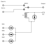
By the way, I just updated my soft-touch code to work with the pedal pcb board schematic and added an option for it to be level-sensitive to watch that combined SW signal... Just in case you just want to use another relay module instead of cobbling a circuit together. Then you can use a latching relay. The code is drastically simplified to be level sensitive instead of the momentary switch. Then the first three modules are wired into the 4th like this. Obviously gross overkill to use an attiny to do this but you get a nice PCB and latching relay to do it. The MAS effects relay module could be used for this, too. It's a smaller PCB but has no control signal, which isn't needed for this 4th switch.

By the way, I just updated my soft-touch code to work with the pedal pcb board schematic and added an option for it to be level-sensitive to watch that combined SW signal... Just in case you just want to use another relay module instead of cobbling a circuit together. Then you can use a latching relay. The code is drastically simplified to be level sensitive instead of the momentary switch. Then the first three modules are wired into the 4th like this. Obviously gross overkill to use an attiny to do this but you get a nice PCB and latching relay to do it. The MAS effects relay module could be used for this, too. It's a smaller PCB but has no control signal, which isn't needed for this 4th switch.

Paul.Ruby
Active member
Paul.Ruby
Active member
I forgot I had some of the modules here. Just built them and verified they work and the above circuits work to drive a normal relay (not a latching relay). The version with a transistor turns on the relay when all the other modules are off. The simpler diode-only circuit turns the relay on when ANY of the others are on.
Also verified my code for the MAS Effects soft relay module works with this. The code is dirt simple and looks for a level on the switch input, either grounded by the diodes or not to engage. This is only if you want latching relays to conserve power across the board or if you don't want to coble together a relay board by hand. I could build this code for either of the Pedal PCB relay boards, too.
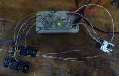
Test rig in action... Two IRBs in control mode (green LEDS) and the MAS Effects board watching the SW lines through a pair of 1n4148 diodes and driving the Yellow LED. The relay is on the other side the MAS board, but, since it is symmetrical, you can mount all the components on the same side as the ATtiny for an application like this. I like the MAS board for it's small size. The extra wires on one IRB was to scope the activity of the ATtiny. It issues 50ms pulses, all active high, to the latching relay and also the CTRL line when being engaged. In CTRL mode, if an IRB is engaged and sees a pulse on CTRL, it disengages 84ms later. Link to MAS Effects module: https://mas-effects.com/relay-bypass/

Last edited:
Paul.Ruby
Active member
Not sure if others have noticed this, but the intelligent relay bypass calls for a 22nf cap across the foot switch inputs. If that is installed, the module doesn't work. The internal pull-up resistor in the ATtiny is too weak to charge that up fast. Would probably work if a stronger pullup resistor was added to the module. Seems to work fine with no cap at all installed. Maybe others have seen this and there is a recommended value? The MAS effect module has no cap at all and uses the internal pull up, but it implements internal software debouncing, which might be different from what is in the PedalPCB code. Since the Pedal PCB code is secret, I don't know.
Paul.Ruby
Active member
I see MAS effects has two boards. One is optimized to be attached directly to a foot switch (the ones I bought) and one that is free standing.
Free standing version: https://shop.mas-effects.com/products/relay-switch-with-digital-controller
Attached to switch: https://shop.mas-effects.com/products/relay-bypass
But they use different assignment of ATtiny IO lines, so I have more code to write. One advantage of the free-standing board is that it's a bit cleaner layout without the useless optocoupler stuff.
Free standing version: https://shop.mas-effects.com/products/relay-switch-with-digital-controller
Attached to switch: https://shop.mas-effects.com/products/relay-bypass
But they use different assignment of ATtiny IO lines, so I have more code to write.
Feral Feline
Well-known member
Cool stuff, @Paul.Ruby; quite the crash course in relay switching, for me.
Still lots of info beyond my ken, but I'm further along the path to understanding thanks to you.
Still lots of info beyond my ken, but I'm further along the path to understanding thanks to you.
benny_profane
Well-known member
I’ve never had a problem with it. Is this behavior consistent for you?Not sure if others have noticed this, but the intelligent relay bypass calls for a 22nf cap across the foot switch inputs. If that is installed, the module doesn't work.
Paul.Ruby
Active member
Yep. If I install 22nf, the module does not work. Works fine without, so I haven't looked back.I’ve never had a problem with it. Is this behavior consistent for you?
Robert
Reverse Engineer
I can't think of any reason the capacitor would cause a problem assuming it's not defective...
I'm not sure if ATMEL specifies the value of the internal pull-up resistor or not, but even if it were 1M (and I highly doubt that it is) that would give a time constant of 22 milliseconds.
The capacitor charges when the footswitch is released, so unless you're stomping again within 22mS ....
Any chance you're using a normally closed footswitch? I know some folks do that to change the trigger from rising to falling edge, and I suppose in that case the duration that the switch is pressed would be more critical.... although still, less than 100mS is some serious stomping unless you're playing a game of "The footswitch is lava".
Paul.Ruby
Active member
The lava game might be the reason. I'm using a test rig (seen above in post #7) with a wire to tap the contact to ground, not an actual foot switch. It's perfect without the cap but doesn't switch reliably with the cap.I can't think of any reason the capacitor would cause a problem assuming it's not defective...
I'm not sure if ATMEL specifies the value of the internal pull-up resistor or not, but even if it were 1M (and I highly doubt that it is) that would give a time constant of 22 milliseconds.
The capacitor charges when the footswitch is released, so unless you're stomping again within 22mS ....
Any chance you're using a normally closed footswitch? I know some folks do that to change the trigger from rising to falling edge, and I suppose in that case the duration that the switch is pressed would be more critical.... although still, less than 100mS is some serious stomping unless you're playing a game of "The footswitch is lava".
Similar threads
- Replies
- 9
- Views
- 823
- Replies
- 9
- Views
- 507
- Replies
- 5
- Views
- 324
- Replies
- 10
- Views
- 737
- Replies
- 2
- Views
- 183


