Digital BBD concept looking for comments and beta testers

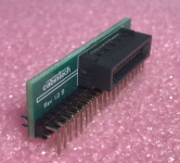
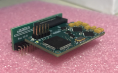
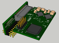
Coming soon, a low profile through-hole adapter for fitting in tight spaces (like most every pedal :)). This reduces the vertical height requirement to about 17mm (0.7in) including the program pin headers. If you want to cut those off it can save about 5mm in height. This give you about 8mmm under the module as useful space on the motherboard.
1715981355883.png
 
Coming soon, a low profile through-hole adapter for fitting in tight spaces (like most every pedal :)). This reduces the vertical height requirement to about 17mm (0.7in) including the program pin headers. If you want to cut those off it can save about 5mm in height. This give you about 8mmm under the module as useful space on the motherboard.

View attachment 75313
Are these available now?
 
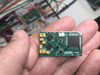
Rev 2.0 of the hardware is in-house! This format and pinout is what we will be using going forward. Instead of the edge connector (got lots of feedback about that) we now have 48 castellated edge pins on 1.4mm centers. This lowers cost (the connector was not cheap), gives a more reliable connection when vibration and road-ruggedness is a concern, and can be easily soldered by hand. This also gave us a few more I/Os to implement some new features.

1723748755438.png

Significant changes in 2.0 modules:
  • Smaller module size, no edge connector (cheaper, more reliable castellated hole I/O)
  • Selectable sampling rates of 48kHz (default), 32kHz, 24kHz, or 12kHz
  • Delay times up to 2.7 seconds (!) with lower sampling rates
  • BBD emulation program (#6) now supports automatic-mode aliasing as an option
  • I/O pinout has changed
  • No on-board jumpers, all configuration is via I/O pins
  • Updatable firmware for new programs and features
  • RESET pin added for changes to primary/secondary mode or sample rate without a power cycle
Here is what the new selectable sampling rate will do:
RATE_1RATE_0Sampling RateMin DelayTotal Max Delay
0012kHz1.16ms2.731s
0124kHz0.58ms1.365s
1032kHz0.44ms1.024s
1148kHz0.29ms0.682s


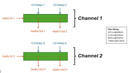
“Total Max Delay” is the total delay time of all channels combined. How this total delay time is divided among the delay channels is defined by the selected program. So delay channels no longer have one fixed maximum delay time in a given program, they have some percentage of the total (which is determined by the selected sampling rate). For example, program #1 is now configuration:

1723750472980.png

Updated data sheet will be available soon. Also working on new DIL adapter for breadboarding and through-hole use, and an updated development / breakout board for the new format and features.
 
Last edited:
Back
Top