Grover drive help

gilmouring

New member
Hey guys,

hope this is the right place to post.
Please try to be lenient, this is my first build.

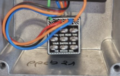
1st question: should I turn this? It says "If you can read this your switch is on the wrong side".
1720722157915.png


2nd question: the guy who sent me the components kit, send some wrong diodes and missed a 120k resistor

1st diode expected was 1N34A (D2) and he sent OA1182 instead
2nd diode expected was 1N4148 (D100) andhe sent 1N5817 (this one I still can't believe it, but 8 years ago I bought some components to build a big muff that I never used...and ta-da! I have the right one. But still curious if they could be swapped (I won't of course)

About the 120K resistor (Would be R9 in the docs), I have a lot of 100K...maybe it's moronic, but can I use a 100K?
I thought about serializing a 100K and a 20K but the space is too tiny...

By the way I opened a claim to the guy, cause I'm still missing the D2...

Here's the result so far
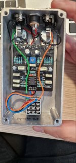

photo_5796279273756148344_y.jpg
 
Ah I almost forgot...from the docs it looks like you need to bridge some pins of the switch..
But I saw the build from another guy here in the forum and it didn't look like he did anything..

Thanks again and sorry for my ignorance, I know almost nothing about electronics!
 
Welcome to the forum.

1. It’s obvious that the 3pdt PCB is on the wrong side. Better to use a new 3pdt and wire it manually like in the build doc.
2. The OA1182 will work as well, any germanium with a forward voltage close to 0,3v will work. BAT46 is often used as well in other Zendrive like pedals. Try the OA1182 first to see how you like it.
The 1n5817 should work as well in the position of the 1n4148.
You can serialize 100k and 20k together and connect them in a V like shape so it will fit. We often do that when we don’t have the exact value in stock or need to create a more exotic resistor value.
 
Last edited:
Ah I almost forgot...from the docs it looks like you need to bridge some pins of the switch..
But I saw the build from another guy here in the forum and it didn't look like he did anything..

Thanks again and sorry for my ignorance, I know almost nothing about electronics!
You don’t need to bridge some pins on the switch when using the 3pdt mini pcb.
Without it you do.

Did you order via Musikding? Klaus has many orders and sometimes makes little mistakes like a missing component.
He will fix the issue but it might take some time.
 
Hey Harmaes,

thanks a lot! Very helpful!
Yes I ordered via Musikding...the guy had the BOM of the 2014 version of the pedal, but the PCB was the latest..
In the meantime Klaus answered he's sending the second and final fix with the 120K and the diode.
But I'll try with the one like you suggested.
About the mini pcb I wouldn't have a replacement....I'll try removing the soldering and turn it..
If I fail I'll make another order for a new one...and while I'm there I'll take some components, maybe for a future build ;)

Thanks again!!
Great, good luck.

Desoldering a mini PCB board is a major pain and you will break the switch probably. I've had more luck cutting it off with some cutting pliers and removing the residu solder joints as quick as possible. Otherwise a new 3PDT is advisable.
And shorten the wires to the 3PDT and make sure that the input and output wires aren't close to elco caps. Position the input/output wires alongside the PCB as shown in the build doc. You can order some longer wire to be able to do that. The wire Klaus is often too short for that.
 
Ok I'm ordering a new 3PTD.
And yes, cable wasn't long enough.
I'm getting some cable as well :)

No I did not know it was a fuzz into a zendrive!!

But I did noticed the 2 transistors and I thought it could be something like that!

I'll take a look at the zendrive circuit out of curiosity!

Can't wait to turn on my Grover...

Thanks again for the tips!
 
Back
Top