Signal generator help

Grover

New member
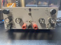
Im very new to the world of electronics and pedal building. However, I’ve recently been given a DIY signal generator from a friend and I’d like to 1) get it working and 2) use it for signal tracing and diagnostics. I already made a probe and am using a phone app for a signal, but I think it would be cool to give my friends old gear some use.

Where do I begin in accomplishing these two goals?
 

Attachments

  • IMG_9482.jpeg
    IMG_9482.jpeg
    498.3 KB · Views: 16
  • IMG_9481.jpeg
    IMG_9481.jpeg
    571.2 KB · Views: 16
  • IMG_9480.jpeg
    IMG_9480.jpeg
    659.6 KB · Views: 16
You've already begun, on the right footing no less by posting pics!

Have you searched online for a schematic for it, or is there one on the inner lid? Try to source scans of the user's manual, too, if the manual didn't come with it.

Next step, visual inspection.
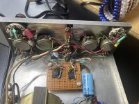
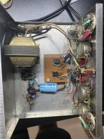
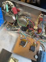
There's an op-amp chip missing, some broken wire-connections — what op-amp, where were the wires connected? (black & red, so power?)

Look for leaking or bulging capacitors. Look at solder jointsl, are any cracked?
Maybe hit the post with some De-Oxit or similar product.

Start with power. Does it fire up and not produce a tone, or is it not firing up at all?


Cool looking unit and I dig the background story behind it. Kudos for resurrecting it instead of letting it rot away.
 
Thank you!

Starting off, no schematic - I think it’s all in his head.

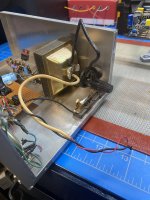
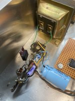
Visual inspection - see picture of the transformer(?). Power comes in from wall, one wire goes into the transformer and the other goes into the glass tube (fuse?!). Then the white/red wire comes out the same side and he’s coiled it with the black wire coming out the other side of the fuse. These two wires aren’t connected to anything. This seems like a good place to start but I don’t know what they should connect to, haha.

Then two wires come out of the other side of the transformer, go through some parts, then split off to the left and right ‘on’ switches of the box, then to the left and circuits on the perf board. So could the left and right side work independently? Yes, there’s a missing oscillator(?) chip on the left side of the perf board. Do you think I can just focus on the right side and trouble shoot that first? What do you think the differences between the two sides are? Both seem to have same switches and pots.
 

Attachments

  • IMG_9484.jpeg
    IMG_9484.jpeg
    531.4 KB · Views: 3
  • IMG_9485.jpeg
    IMG_9485.jpeg
    492 KB · Views: 3
  • IMG_9486.jpeg
    IMG_9486.jpeg
    556.2 KB · Views: 3
If you can get your buddy to draw up a schematic, that would be an awesome place to start.

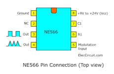
If I were you, I'd start with power, then move on to the signal generator. Do the chips have power? A simple google search can tell you which pins to check (pin 8 in this case). If not, i'd start there and work backwards up until the transformer. There may be a bad (or no) connection.
1721835022881.png
 
I couldn't immediately tell you the differences between the two sides, nor even make a guess and even after researching this thoroughly I might not be able to fathom it.

What I would do, is trace it out and draw my own schematic. That would help me make more sense of it, and get that much closer to being able to answer the questions you raised, and figure out the missing pieces to the puzzle.


BuddytheReow raises an important distinction: it was my understanding that your friend had this DIY project, but not necessarily that your friend was the maker/designer of the circuit as BtR suggests and you seem to confirm by saying it's all in his head. So your friend came up with this and didn't give you a schematic?

Nonetheless, it would be a good opportunity to practice your own tracing and schematic skills.
 
Thanks, All. It lives!

I ended up checking the resistance on each end of transformer, it was good. I then reconnected the hot wires and got 19ish volts coming out of it and figured i’d give it a whirl. I was able to get a faint sound out of one side of it. Still not sure how to make use of all its functions, but I think it should accomplish my goals of recommissioning it for my simple and limited needs of pedal diagnostics. It kicks out a sine wave, good enough.

Thanks again for the ideas and support.
 
If you are looking to learn via a science project, keep following the prior advice. However, if you are just in need of a quick and reliable signal generator, there are a few good free phone apps. I use 'PA Tone' with 1/8" plug into my phone's headphone jack, terminating to an RCA / 1/4" plug as my signal generator.
 
Back
Top