CELSIUS PREAMP KIT - ISSUE

Artheril

New member
Hey,

I started to build my Celsius preamp kit, but got a problem I can't solved.

True bypass seems good, because if the pedal is not power, the sound of the guitar come from the amp.
But when I plugged the 9v DC jack, a loud "buzz"appears and no guitar sound, while the effect is on ON or OFF.
However, when the effect is turned on, the led is shinning.

Do you have any ideas to solve this ?

Thanks
 

Attachments

  • 1.jpeg
    1.jpeg
    752.5 KB · Views: 43
  • 2.jpeg
    2.jpeg
    639.4 KB · Views: 47
  • 3.jpeg
    3.jpeg
    673.9 KB · Views: 50
  • 4.jpeg
    4.jpeg
    529.4 KB · Views: 47
Your input and output jacks are wired incorrectly. The yellow wires connected to the ground pads on the board are connected to the signal connectors on the sockets. If you reverse those connections on the sockets you should get better results
 
For your wires to the board try a different approach to get better connections. First demantle the wire for 5 mm, the twist the strands until you get a straight bundle, then hit it with a bit solder. This sold piece is easy to stick thru the holes and can be soldered to the board.
 
Your input and output jacks are wired incorrectly. The yellow wires connected to the ground pads on the board are connected to the signal connectors on the sockets. If you reverse those connections on the sockets you should get better results
I still dont have any sound effect when the effect is ON, but at least there are no more "buzz", thank you for your advice !
 
Okay then clean your build: Remove the stray wires. Look for bad connections and shorts. Reflow the connections. Use good light and magnifing glas (ask me how i know).
 
The wiring I'm lost on. Seems a odd choice but that needs to be cleaned up. The soldering on the dpdt switch needs to be fixed and I would reflow every solder joint. But I'm pretty sure you soldered the IC in the wrong orientation
 
I agree, it looks like both IC's are backwards.
1725192900061.png


The wiring I'm lost on.

I've seen this done on one other build.

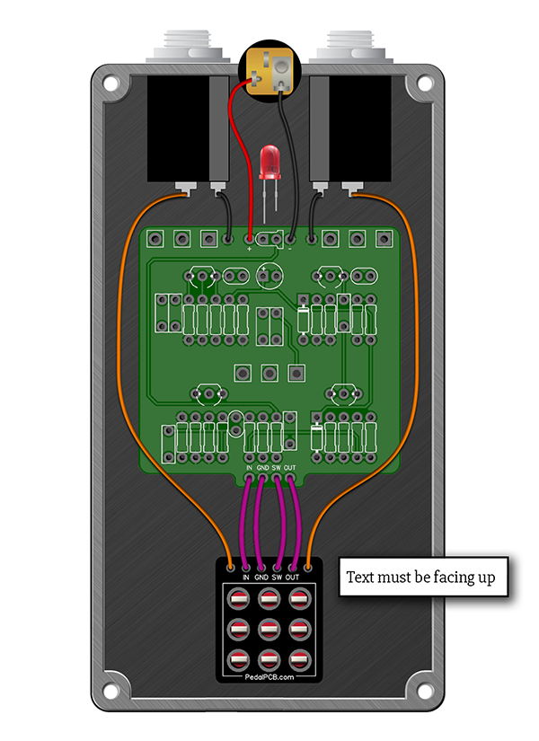
You should use the 3PDT breakout board or the wiring diagram in the build doc, not both. The breakout board takes care of all of the pesky jumpering across the 3PDT, you just wire it directly pin for pin to the Celsius PCB. (IN/GND/SW/OUT)

3PDT.png
 
I agree, it looks like both IC's are backwards.


I've seen this done on one other build.

You should use the 3PDT breakout board or the wiring diagram in the build doc, not both. The breakout board takes care of all of the pesky jumpering across the 3PDT, you just wire it directly pin for pin to the Celsius PCB. (IN/GND/SW/OUT)

3PDT.png
But the IC should be desoldered and put in right. The dot is at pin 5
 
I want to thank you all for taking time to advice me, I really appreciate and it's very helpful !
As I couldn't correctly desoldered the ICs, they got broken so I just ordered new ones, I'm waiting few days to get them.
I'll tell you later if I finally managed to make the pedal working, but thank you very much again
 
1000006010.jpg

This is a thing of beauty. If I were you, I'd get this photo printed and framed up.

It'll be a comforting reminder for how far you've come in years to come. I wish I had a photo of my first BYOC build.

Magnifique.
 
Back
Top