There seems to be a fair amount of interest on this board for parallel mixers. I know that makes an appearance in the Wish List forum. I've asked Robert about the possibility that one will be forthcoming, but no answer. It sounds like one is in the works, but it's not soup yet. Darn. My perfect parallel mix pedal would have the ability to mix two separate effects channels in parallel, each with their own phase reverse switch, with a clean channel and separate level pots for each channel. If this sounds familiar, it's the Old Blood Noise Signal Blender (which is actually pretty reasonably priced, but I'd like to build my own).
The Guitar PCB ParaMix appears to be nearly what I am looking for, but not quite close. And their documentation is pretty confusing really (They show you how to wire two stomp switches but the picture shows three?). He implies that you can blend three signals together, but really you can only blend one effects pedal in parallel, and the other would be in series with the clean signal, basically no different than plugging it front of or after the Paramix pedal. But in any case, you have to sacrifice your clean signal to use it.
I bought three of their PCBs to play around with. The first one I plan on building stock. But the others, I'd like to mess with. I think I can find a way using some offboard wiring and Vero board to fly in a couple circuit blocks to accomplish what I'm trying to do.
I've attached a PDF of a schematic of what I'd like to do.

I've already breadboarded the first section of the TL074 that splits the signal three ways and it seems like there's enough buffering to provide a clear signal for all three sends. The effects returns each have a recovery stage but the clean channel doesn't. I've put together a Runoff Groove JFET recovery stage circuit and breadboarded it so I can drop that in pretty easily on an offboard Vero. The Clean channel after the splitter junction and the Send B section would have to be constructed on a Vero board and so would the phase switching for Return B (or I could hang it from the switch). Otherwise, I'm not really seeing a major problem.
If I'm reading the GuitarPCB schematic correctly, the VCC points are about 4.5 volts. I'm guessing that's a bias voltage? (I can't find a Vb schematic symbol on Diptrace, but this seems to work for me).
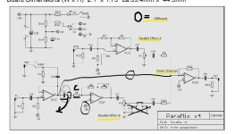
Here is the GuitarPCB schematic with a couple of my notes on it. I've highlighted the components that I think I can either move to an offboard circuit block or eliminate.

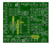
And here's the board. Highlights are the junctures where offboard components would be flown in. With IC pin #3 it will be a little bit tricky: I'd have to bend the leg out and insert a resistor into the socket and then solder the resistor directly to IC pin 3. It will look wonky, but I think it will get the job done.

I realize this could easily turn into a wiring nightmare, but I suspect it's already going to be challenging anyway. And besides, it's a spare PCB.
Can anyone with more experience weigh in and point out anything I may be missing? I was wondering if trim pots on each channel would be helpful too just to set some internal gain. I'm kinda afraid that I'll get some disparities in the output levels on this and won't have an option to fix it.
The Guitar PCB ParaMix appears to be nearly what I am looking for, but not quite close. And their documentation is pretty confusing really (They show you how to wire two stomp switches but the picture shows three?). He implies that you can blend three signals together, but really you can only blend one effects pedal in parallel, and the other would be in series with the clean signal, basically no different than plugging it front of or after the Paramix pedal. But in any case, you have to sacrifice your clean signal to use it.
I bought three of their PCBs to play around with. The first one I plan on building stock. But the others, I'd like to mess with. I think I can find a way using some offboard wiring and Vero board to fly in a couple circuit blocks to accomplish what I'm trying to do.
I've attached a PDF of a schematic of what I'd like to do.

I've already breadboarded the first section of the TL074 that splits the signal three ways and it seems like there's enough buffering to provide a clear signal for all three sends. The effects returns each have a recovery stage but the clean channel doesn't. I've put together a Runoff Groove JFET recovery stage circuit and breadboarded it so I can drop that in pretty easily on an offboard Vero. The Clean channel after the splitter junction and the Send B section would have to be constructed on a Vero board and so would the phase switching for Return B (or I could hang it from the switch). Otherwise, I'm not really seeing a major problem.
If I'm reading the GuitarPCB schematic correctly, the VCC points are about 4.5 volts. I'm guessing that's a bias voltage? (I can't find a Vb schematic symbol on Diptrace, but this seems to work for me).
Here is the GuitarPCB schematic with a couple of my notes on it. I've highlighted the components that I think I can either move to an offboard circuit block or eliminate.

And here's the board. Highlights are the junctures where offboard components would be flown in. With IC pin #3 it will be a little bit tricky: I'd have to bend the leg out and insert a resistor into the socket and then solder the resistor directly to IC pin 3. It will look wonky, but I think it will get the job done.

I realize this could easily turn into a wiring nightmare, but I suspect it's already going to be challenging anyway. And besides, it's a spare PCB.
Can anyone with more experience weigh in and point out anything I may be missing? I was wondering if trim pots on each channel would be helpful too just to set some internal gain. I'm kinda afraid that I'll get some disparities in the output levels on this and won't have an option to fix it.
Attachments
Last edited:


